
Elastic wave splitter having a resonant circuit between an antenna terminal and ground

a technology of elastic wave and splitter, which is applied in the field of splitters, can solve the problems of difficult to reduce the size of the splitter, generate intermodulation distortion (imd), and reduce so as to increase the size of the elastic wave splitter, improve the frequency characteristics of the splitter, and increase the resistance loss

Active Publication Date: 2016-10-04
MURATA MFG CO LTD
View PDF13 Cites 1 Cited by
  • Summary
  • Abstract
  • Description
  • Claims
  • Application Information

AI Technical Summary

Benefits of technology

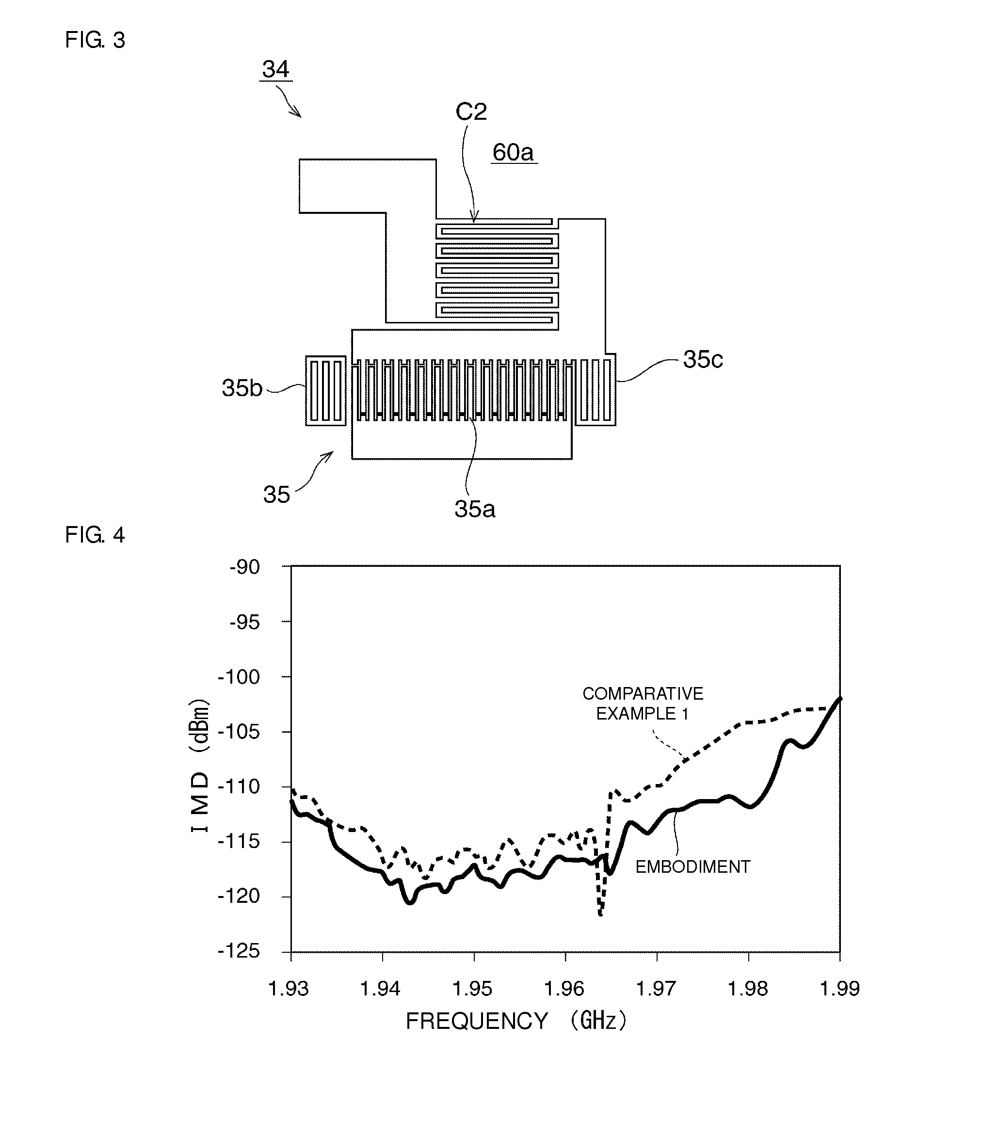
Significantly reduces intermodulation distortion while maintaining low insertion loss and compact size by effectively attenuating interference waves within the specified frequency band.

Problems solved by technology

In such elastic wave resonator filters, intermodulation distortion (IMD) is generated due to the nonlinearity of the filters.
In addition, degradation of filter characteristics is a problem.
However, in the splitter 1001 described in Japanese Unexamined Patent Application Publication No. 2010-21914, the areas of the resonators are increased and therefore it is difficult to reduce the size of the splitter 1001.
In addition, resistive loss is increased and therefore, there has been a problem in that insertion loss is increased.

Method used


Image

  • Elastic wave splitter having a resonant circuit between an antenna terminal and ground
  • Elastic wave splitter having a resonant circuit between an antenna terminal and ground
  • Elastic wave splitter having a resonant circuit between an antenna terminal and ground

Examples


second preferred embodiment

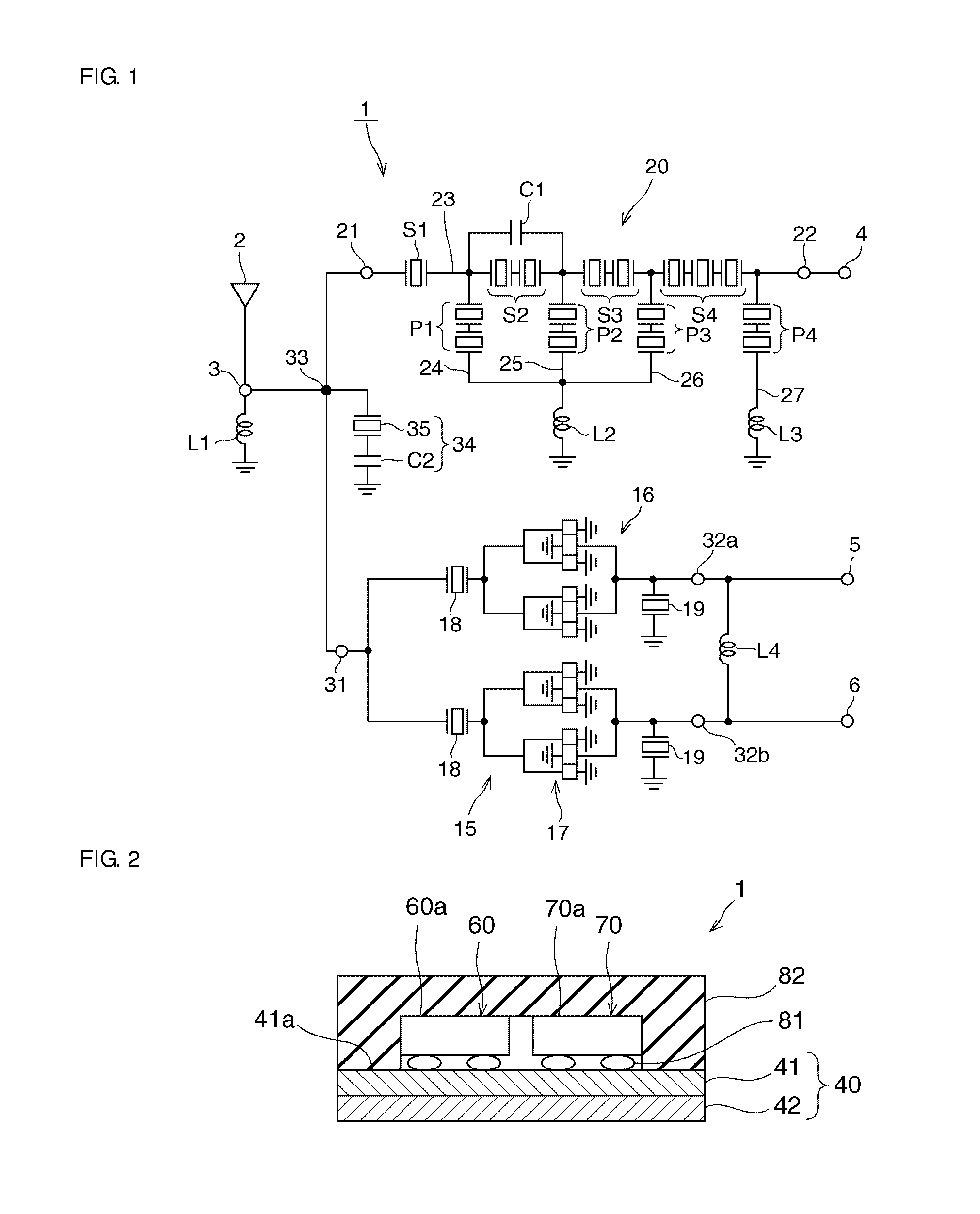
[0075]FIG. 12 is a schematic circuit diagram of an elastic wave splitter according to a second preferred embodiment of the present invention. Elements that are the same as those in the first preferred embodiment are denoted by the same reference symbols, their description in the first preferred embodiment is to be referred to and detailed description thereof will be omitted.

[0076]In this preferred embodiment, a second single-terminal-pair surface acoustic wave resonator 36 is connected in parallel with the single-terminal-pair surface acoustic wave resonator 35 in the resonant circuit 34. The wavelength of the IDT electrode in the second single-terminal-pair surface acoustic wave resonator 36 is relatively large compared to that of the first single-terminal-pair surface acoustic wave resonator 35. That is, the resonant frequency of the second single-terminal-pair surface acoustic wave resonator 36 is positioned further toward the low frequency side than the resonant frequency of the...

third preferred embodiment

[0080]FIG. 14 is a schematic circuit diagram of an elastic wave splitter according to a third preferred embodiment of the present invention. Elements the same as those in the first preferred embodiment are denoted by the same reference symbols, their description in the first preferred embodiment is to be referred to and detailed description thereof will be omitted.

[0081]In this preferred embodiment, a third single-terminal-pair surface acoustic wave resonator 38 is connected in series with the single-terminal-pair surface acoustic wave resonator 35 in the resonant circuit 34. The wavelength of the IDT electrode of the third single-terminal-pair surface acoustic wave resonator 38 is longer than that of the first single-terminal-pair surface acoustic wave resonator 35. That is, the resonant frequency of the third single-terminal-pair surface acoustic wave resonator 38 is positioned farther toward the low-frequency side than the resonant frequency of the first single-terminal-pair surf...


PUM


Abstract

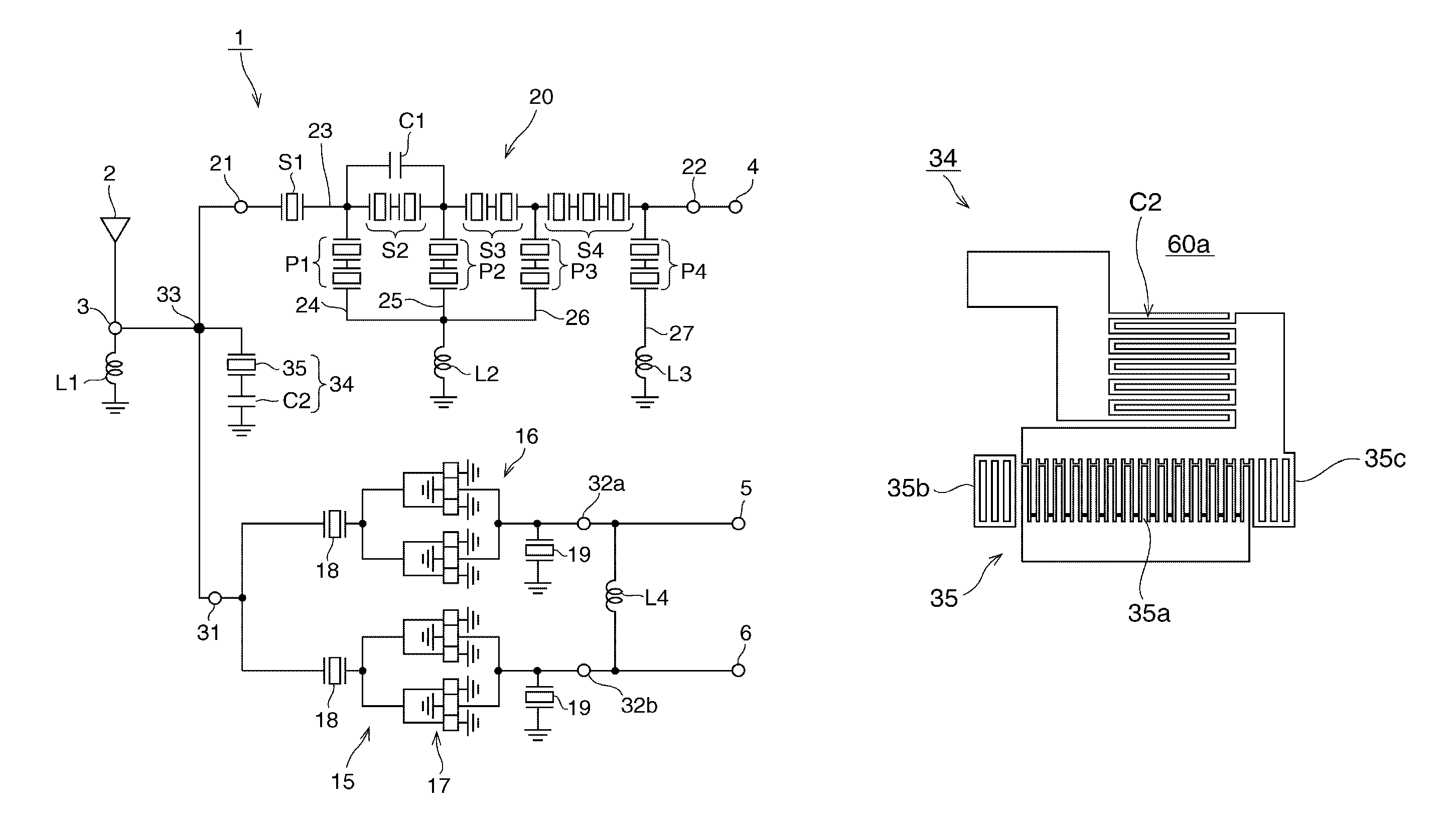
An elastic wave splitter includes an antenna terminal, a transmission terminal and reception terminals. A transmission filter is connected between the antenna terminal and the transmission terminal. A reception filter is connected between the antenna terminal and the reception terminals. The transmission filter and the reception filter are each defined by an elastic wave filter. A resonant circuit is connected between the antenna terminal and a ground potential. The resonant circuit includes a surface acoustic wave resonator and a capacitor connected in series with the surface acoustic wave resonator. A resonant frequency of the resonant circuit is positioned in a frequency band of an interference wave that causes intermodulation distortion to be generated.

Description

BACKGROUND OF THE INVENTION[0001]1. Field of the Invention[0002]The present invention relates to splitters that use elastic waves such as surface acoustic waves, boundary acoustic waves or bulk elastic waves, and in particular relates to elastic wave splitters that include a transmission filter and a reception filter defined by elastic wave filters.[0003]2. Description of the Related Art[0004]In recent years, splitters using elastic wave resonator filters have been widely used as splitters in communication devices. Examples of such an elastic wave resonator include a bulk elastic wave resonator filter, a surface acoustic wave resonator filter and a boundary acoustic wave resonator filter.[0005]In such elastic wave resonator filters, intermodulation distortion (IMD) is generated due to the nonlinearity of the filters. In addition, degradation of filter characteristics is a problem.[0006]In Japanese Unexamined Patent Application Publication No. 2010-21914, a splitter is disclosed havi...

Claims


Application Information

Patent Timeline
Patent Type & Authority Patents(United States)
IPC IPC(8): H03H9/72H03H7/46H03H9/64H03H9/05H03H9/00
CPCH03H9/725H03H7/461H03H9/6489H03H9/0004H03H9/0576H03H9/6483
Inventor FUJITA, SHIGEYUKI
Owner MURATA MFG CO LTD
Learn More