Access assembly for anterior and lateral spinal procedures

a technology for accessing and lateral spinal cords, applied in the field of anterior and lateral spinal cord stabilization, can solve the problems of pain, loss of function, complete paralysis of legs, loss of bowel and bladder control,

Active Publication Date: 2016-10-11
INTEGRITY IMPLANTS INC
View PDF124 Cites 19 Cited by
  • Summary
  • Abstract
  • Description
  • Claims
  • Application Information

AI Technical Summary

Benefits of technology

[0015]The dynamic tube assembly includes an outer tube member and an inner lock member. The inner lock member includes an inner bore sized for cooperation with the outer surface of the distractor member. In this manner, the distractor acts as a guideway for the dynamic tube assembly. The dynamic tube assembly is constructed and arranged so that a portion of the lock member and outer tube member extend a short distance into the disc space adjacent the side surfaces of the distractor and between the two opposed surfaces. The lock member is then rotatable to engage the opposing bony surfaces of the disc space. In this manner, the lock member secures the first end of the dynamic tube assembly into place and releases the distractor member for extraction from the patient through the bore of the dynamic tube assembly. In some embodiments the lock member may include a shaped cam surface that provides additional controlled distraction of the disc space during rotation thereof. The locking function prevents the first end of the dynamic tube assembly from being inadvertently moved from its intended position once placed, while maintaining the adjacent vertebrae in a distracted position and aligned position. Once the dynamic tube assembly is in place within the patient, the distractor and guide wire may be removed, providing an access tunnel to the disc space. The tunnel is provided with sufficient diameter for disc modification or removal as well as the placement of spacers, bone fragments, implants and the like to be passed therethrough to the disc space. Once the operation is completed, rotation of the lock member releases the dynamic tube assembly for removal from the patient.
[0021]It is still yet another objective of the present invention to provide a device and method to achieve discectomy, fusion and interbody stabilization of the lumbar without the need to mobilize the great vessels from the front of the vertebral bodies.
[0023]It is still yet another objective of the present invention to provide a device for performing surgery on the spine that includes a cam surface for providing controlled distraction of a disc space.

Problems solved by technology

A disc herniation may compress the spinal cord and / or nerve roots and cause pain, loss of function, and even complete paralysis of the legs with loss of bowel and bladder control.
However, this has proven both difficult and quite dangerous.
Therefore, the amount of disc removal may be limited.
Sometimes, for a variety of reasons, including the removal of disc material, the thoracic spine may become unstable (too much motion) at any given level.
Thus, the prior art includes numerous drawbacks which have not been entirely addressed.
Although this so-called “open” surgical technique has successfully treated non-unions, instability, injuries and disease of the spine, it is not without disadvantages.
Given the invasive nature of this technique, a lengthy healing time and considerable post-operative pain for the patient is common.
While it is possible to also decompress a posterior disc herniation in the lumbar spine from an anterior approach (from the front), doing so requires the removal of a very substantial portion or all of the disc material in the front and mid portions of the disc, thus leaving that disc and that spinal segment generally unstable.
Interbody fusion from the posterior approach, while still in use, has been associated with significant complications generally related to the fact that the delicate dural sac and the spine nerves cover the back of the disc space and are thus clearly at risk for damage with such an approach.
Regardless of which approach to the front of the spine is used, and apart from the obvious dangers related to the dense anatomy and vital structures in that area, there are at least two major problems specific to the anterior interbody fusion angle of implant insertion itself.
First, generally at the L.sub. 4 and L.sub. 5 discs, the great iliac vessels bifurcate from the inferior vena cava and lie in close apposition to and covering that disc space, making fusion from the front both difficult and dangerous.
Secondly, anterior fusions have generally been done by filling the disc space with bone or by drilling across the disc space and then filling those holes with shaped implants.
An attempt to get good fill of the disc space places the sympathetic nerves along the sides of the disc at great risk.
Alternatively, when the dowel technique is used, because of the short path from the front of the vertebrae to the back and because of the height of the disc as compared to the width of the spine, only a portion of the cylindrical implant or implants actually engage the vertebrae; thus compromising the support provided to the vertebrae and the area of contact provided for the fusion to occur.
Further, the size of the implants are limited by the dural sac posteriorly, and the width of the spine and the delicate vital structures therewith associated anteriorly.

Method used


Image

  • Access assembly for anterior and lateral spinal procedures
  • Access assembly for anterior and lateral spinal procedures
  • Access assembly for anterior and lateral spinal procedures

Examples


Embodiment Construction

[0041]While the present invention is susceptible of embodiment in various forms, there is shown in the drawings and will hereinafter be described a presently preferred embodiment with the understanding that the present disclosure is to be considered an exemplification of the invention and is not intended to limit the invention to the specific embodiments illustrated.

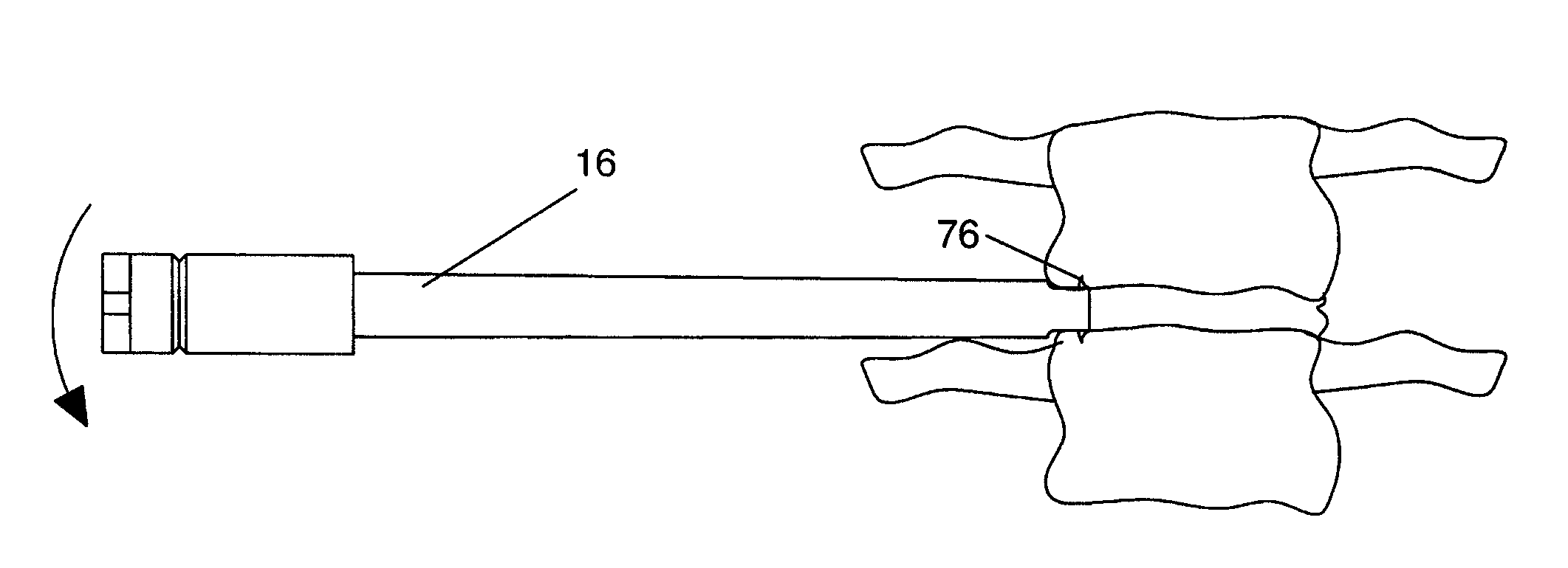
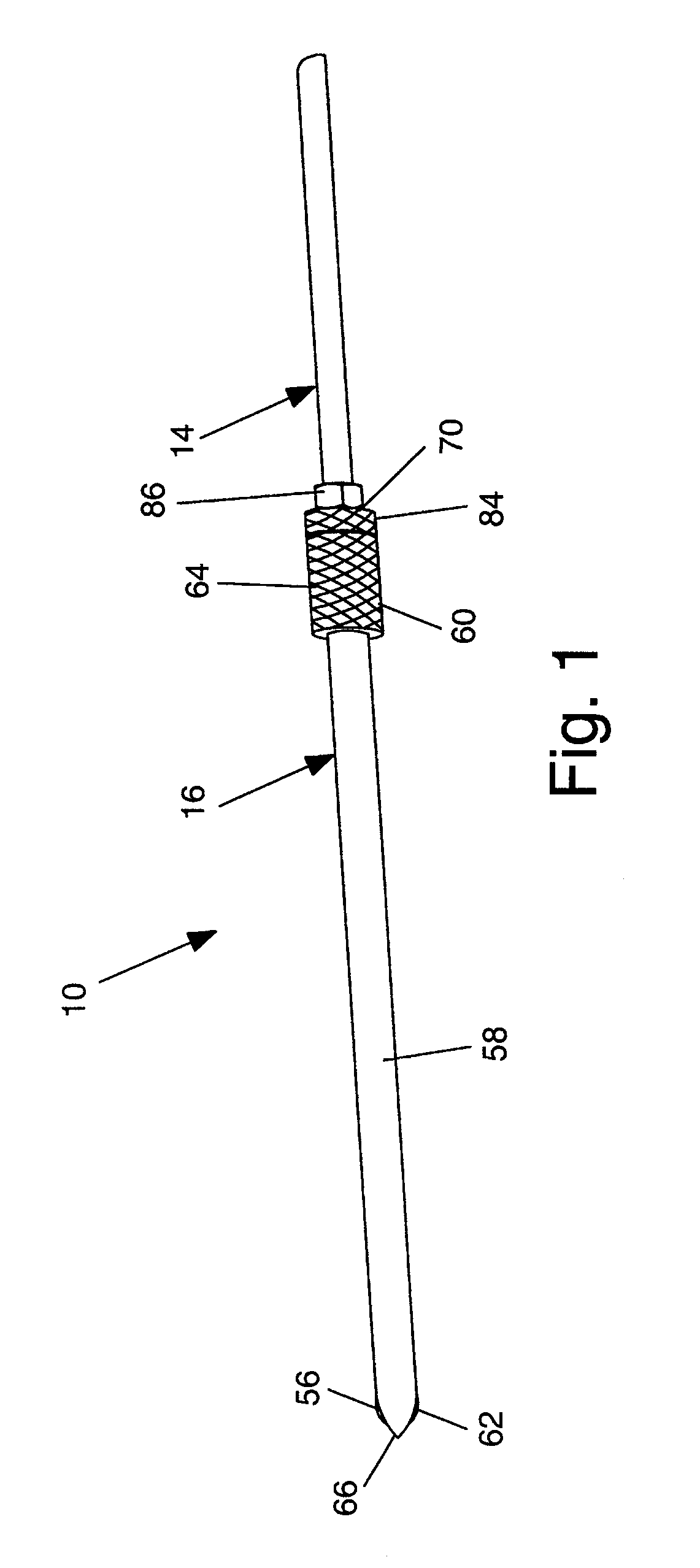
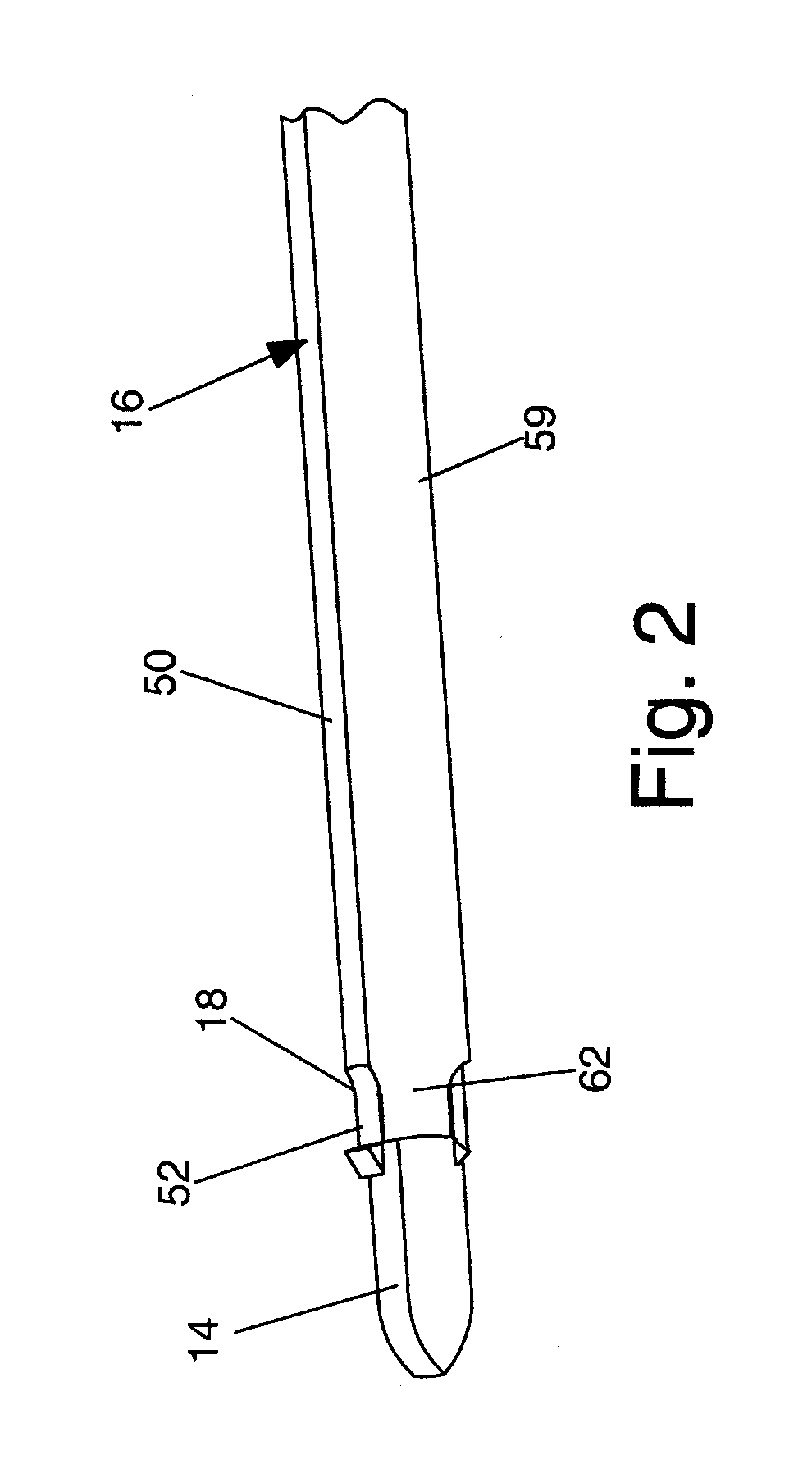
[0042]Referring generally to FIGS. 1-16, an access assembly 10 constructed and arranged for anterior, lateral anterolateral spinal procedures is illustrated. The present invention provides for the entire surgical procedure to be performed through a relatively small incision, and may be performed in either the thoracic or lumbar spine. In the preferred embodiment, the access assembly 10 comprises a guide wire 12, a distractor 14, and a dynamic tube assembly 16 that includes a manually operable locking member 18 for securing the dynamic tube assembly to a bony structure.

[0043]The guide wire 12 is provided for initial inser...


PUM


Abstract

Briefly, the present invention is directed to methods and instrumentation for performing surgery on the spine along its lateral aspect (side) and generally by a lateral, anterior or an anterolateral surgical approach, such that the instruments enter the body from an approach that is other than posterior and make contact with the spine along its lateral aspect. The present invention provides for the entire surgical procedure to be performed through a relatively small incision and may be performed in either the thoracic or lumbar spine.

Description

CROSS REFERENCE TO RELATED APPLICATION[0001]In accordance with 37 C.F.R 1.76, a claim of priority is included in an Application Data Sheet filed concurrently herewith. Accordingly, under 35 U.S.C. §119(e), 120, 121, and / or 365(c) the present invention claims priority of U.S. Patent Application No. 61 / 585,724, entitled “ACCESS ASSEMBLY FOR ANTERIOR AND LATERAL SPINAL PROCEDURE”, filed on Jan. 12, 2012. The contents of each of the above referenced applications are herein incorporated by reference in its entirety.FIELD OF INVENTION[0002]The present invention relates generally to stabilization of adjacent bony structures of the spine and more particularly to an assembly and method for providing anterior and / or lateral access to the disc space of the vertebrae for providing stabilization to the bony structures thereof.BACKGROUND INFORMATION[0003]It is widely held that healing and / or structural correction is greatly facilitated when a bone is stabilized in the proper position. Various dev...

Claims


Application Information

Patent Timeline
Patent Type & Authority Patents(United States)
IPC IPC(8): A61B17/70A61B17/17A61B17/02
CPCA61B17/708A61B17/7074A61B17/1757A61B2017/0256A61B17/8897
Inventor GEIST, WYATT DRAKE
Owner INTEGRITY IMPLANTS INC
Why Eureka
Try Eureka