Flow adjusting device with a button

a technology of adjusting device and button, which is applied in the direction of valve operation/release device, mechanical apparatus, spraying apparatus, etc., can solve the problems of increasing the space occupied by the controller and needing more pressure for

Active Publication Date: 2016-10-18
XIAMEN SOLEX HIGH TECH IND CO LTD
View PDF17 Cites 20 Cited by
  • Summary
  • Abstract
  • Description
  • Claims
  • Application Information

AI Technical Summary

Benefits of technology

[0003]The present invention is provided with a flow adjusting device with a button, which overcomes the problems of the water flow rate controller that it occupies more space and it needs more pressure force.
[0021]1. The sliding direction of the movable shaft and the pushing rod is parallel to the water flowing direction, the structure is clever, the axial size of the fixation unit is small, it occupies small space to release the user's press force, the switch is convenient;2. The inclined surface of the button is coupled to and contacted to the inclined surface of the pushing rod to realize the linkage of the button and the pushing rod, the pressing is convenient;3. The movable shaft is moved between a first position and a second position, the control end is separated from the central waterway when the movable shaft is situated in the first position, the discharge area is the section area of the central waterway, so that the water flow rate is large; the control end is plugged into the central waterway when the movable shaft is situated in the second position, the discharge area is the section area of the clearance of the control end and the central waterway, so that the water flow rate is small to be water saving;4. The control end of the movable shaft is extended out of the assembly cavity in a sealing way, the switch is waterless and saving labor with long life;5. The fixation unit includes a fixation shaft, an outlet and a terminal, the structure is clever and convenient for assembly and manufacture;6. The housing is disposed with an opening, the outlet is assembled inside the housing through the opening, and it is convenient to assemble; the edge of the opening of the housing is disposed with a lock catch, the periphery of the terminal is disposed with a lock groove, the lock catch is locked to the lock groove for convenience to fix every component of the fixation unit.

Problems solved by technology

However, it has disadvantages as below: 1. the sliding direction of the switch button is vertical to the water flowing direction, so that the controller increases the space occupied, especially in a shower; 2. the sliding direction of the switch button is vertical to the water flowing direction, so that it needs more pressure force.

Method used


Image

  • Flow adjusting device with a button
  • Flow adjusting device with a button
  • Flow adjusting device with a button

Examples


Embodiment Construction

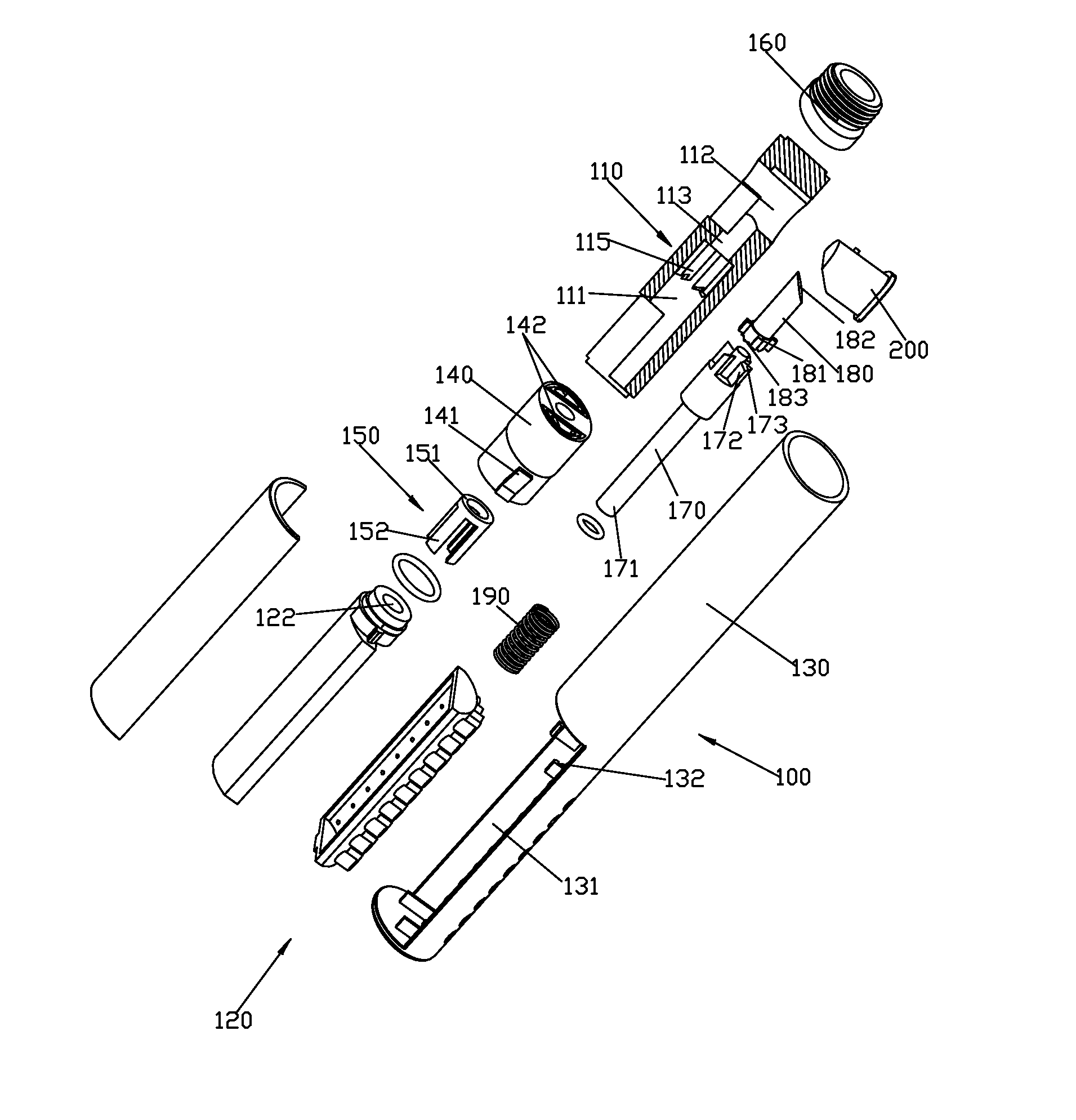
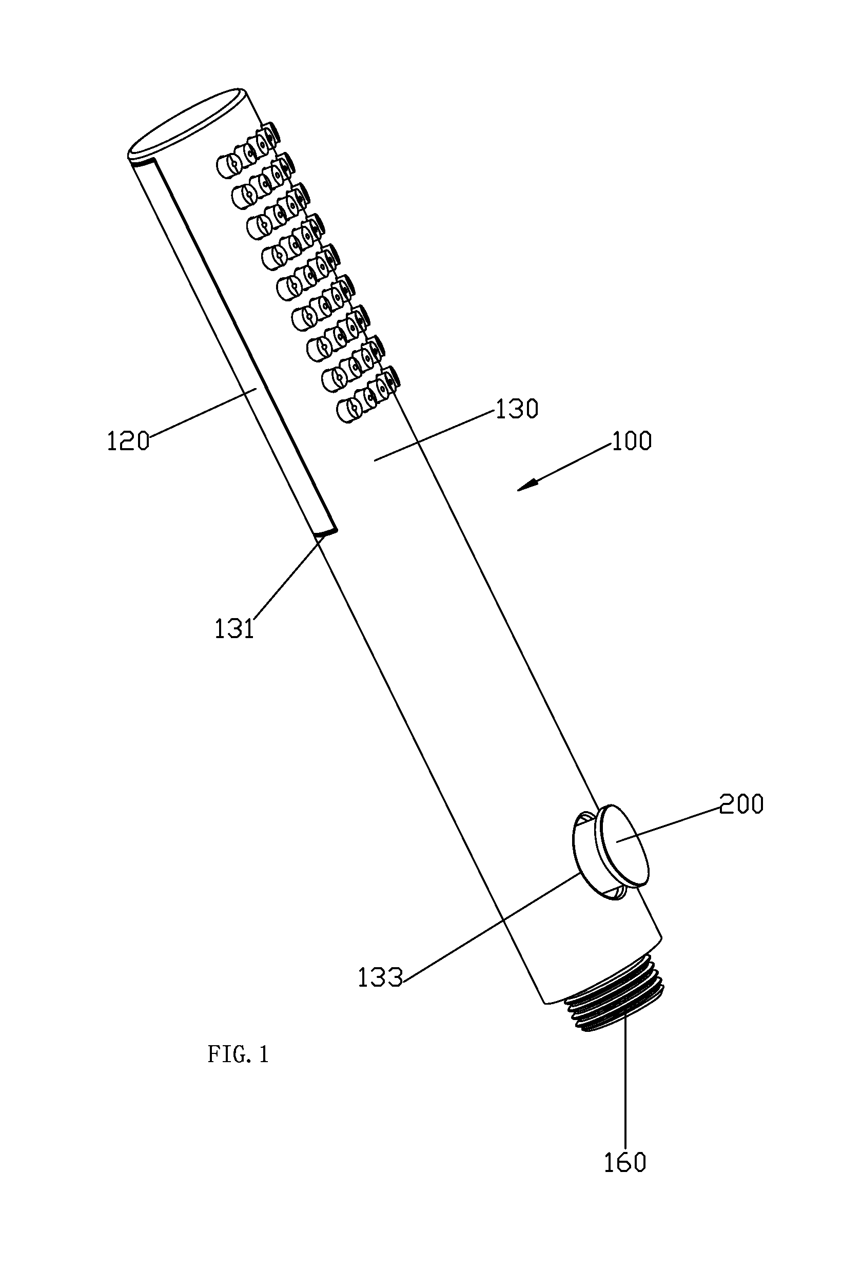
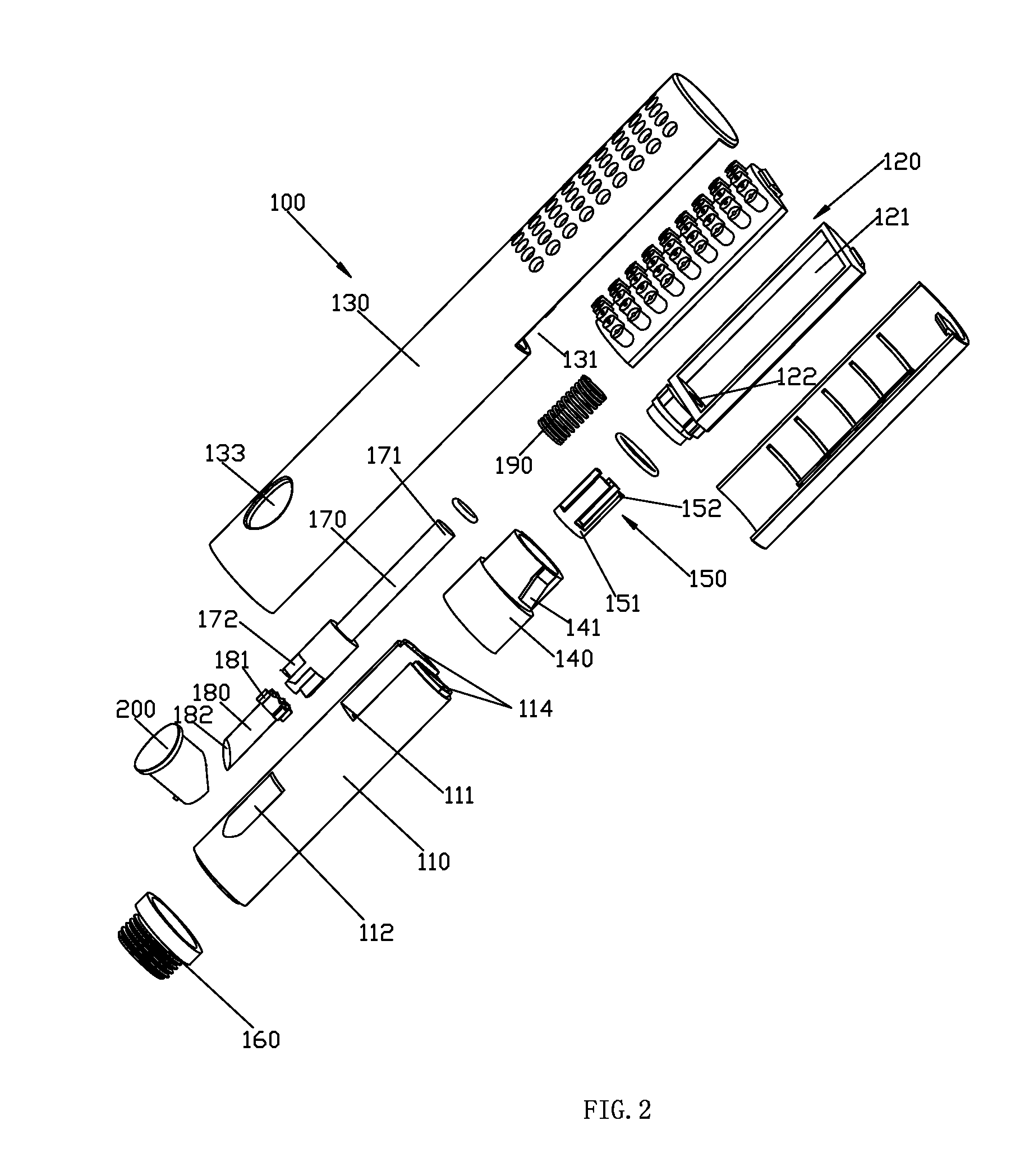
[0030]Refer to the FIG. 1 to FIG. 7 of a flow adjusting device with a button, which is disposed with a fixation unit 100 and a button 200.

[0031]The fixation unit 100 includes a fixation shaft 110, an outlet 120, a housing 130, a terminal 140, a limited body 150 and a plug 160.

[0032]The fixation shaft 110 is assembled inside the housing 130, the external diameter of the fixation shaft 110 is coupled to the internal diameter of the housing 130; the plug 160 is fixed to the first end of the housing 130 inside and withstood the first end of the fixation shaft 110 to prevent the fixation shaft 110 separating from the housing 130; the fixation shaft 110 is connected to the water resource, such as a water pipe, through the plug 160.

[0033]The second end of the housing 130 is disposed with an opening 131, which is disposed with a lock catch 132. The housing 130 is further disposed with a throughout hole 133 throughout inside and outside. The terminal 140 is disposed with a stepped revolution...


PUM


Abstract

A flow adjusting device includes a fixation unit with a waterway and a button; the fixation unit is disposed with a movable shaft, a pushing rod and a spring, the movable shaft and the pushing rod can move relatively to the fixation unit, the motion direction is parallel to the flowing direction of the water in the waterway, the discharge area of the waterway is changed by the relative motion of the movable shaft and the fixation unit to adjust the flow rate, thereinto, the fixation unit, the movable shaft, the pushing rod and the spring are cooperated to form an automatic ball-point pen like movable mechanism; the button is connected to the fixation unit in a sliding way, the sliding direction of the button is vertical to that of the movable shaft, the button and the end of the pushing rod are formed a linkage construction.

Description

FIELD OF THE INVENTION[0001]The present invention relates to a shower device, especially to a flow adjusting device with a button.BACKGROUND OF THE INVENTION[0002]A patent for invention is disclosed in the Chinese patent database in the Nov. 17, 2008 with application number ZL200820016925.5 named a flow rate controller. The controller is disposed with a body disposed with a groove, an inlet disposed in the body and an outlet, a switch button a and a switch button b disposed inside the body, a restoring spring, a constant pressure sealing ring, a water diversion body with an outlet hole and outlet, a sealing ring and a switch button disposed in the switch button a; the switch button a is engaged to the switch button b, the restoring spring, the constant pressure sealing ring and the water diversion body are disposed below the switch button b, the sealing ring is disposed below the water diversion body; the flange at the upper end of the switch button b can be slide along the groove o...

Claims


Application Information

Patent Timeline
Patent Type & Authority Patents(United States)
IPC IPC(8): F16K31/00F16K31/44B05B1/18E03C1/04B05B1/30
CPCF16K31/44B05B1/18B05B1/185B05B1/3026E03C1/0409B05B1/3013
Inventor ZHOU, HUASONGSUN, XIAOZHAOCHEN, WENXINGLI, RENZHONG
Owner XIAMEN SOLEX HIGH TECH IND CO LTD
Why Eureka
Try Eureka