Linearity performance for multi-mode power amplifiers

a power amplifier and multi-mode technology, applied in amplifiers, amplifier details to increase power/efficiency, amplifiers with semiconductor devices/discharge tubes, etc., can solve problems such as and the reversal of gain and phase droop associated with the driver stag

Active Publication Date: 2016-10-18
SKYWORKS SOLUTIONS INC
View PDF3 Cites 8 Cited by
  • Summary
  • Abstract
  • Description
  • Claims
  • Application Information

AI Technical Summary

Benefits of technology

[0007]In accordance with some implementations, the present disclosure relates to a power-amplifier (PA) including a PA circuit that includes a bipolar junction transistor (BJT) having a base, a collector and an emitter. The BJT is configured to receive a radio-frequency (RF) signal through an input path and amplify the RF signal. The PA further includes a biasing circuit in communication with the PA circuit. The biasing circuit is configured to provide a first bias signal or a second bias signal to the PA circuit for operation in a first mode or a second mode, respectively. Each of the first bias signal and the second bias signal is routed to the BJT through a path that includes a common node and a ballast. The PA further includes a linearizing circuit implemented between the common node and a node along the input path. The linearizing circuit is configured to provide a coupling path between the common node and the input path to improve linearity of the PA circuit operating in the first mode while allowing the ballast to be sufficiently robust for the PA circuit operating in the second mode.

Problems solved by technology

The selected level of increased RF power resulting in the conduction through the emitter follower can result in a reversal of gain and phase droop associated with the driver stage.

Method used


Image

  • Linearity performance for multi-mode power amplifiers
  • Linearity performance for multi-mode power amplifiers
  • Linearity performance for multi-mode power amplifiers

Examples


Embodiment Construction

[0060]The headings provided herein, if any, are for convenience only and do not necessarily affect the scope or meaning of the claimed invention.

Introduction:

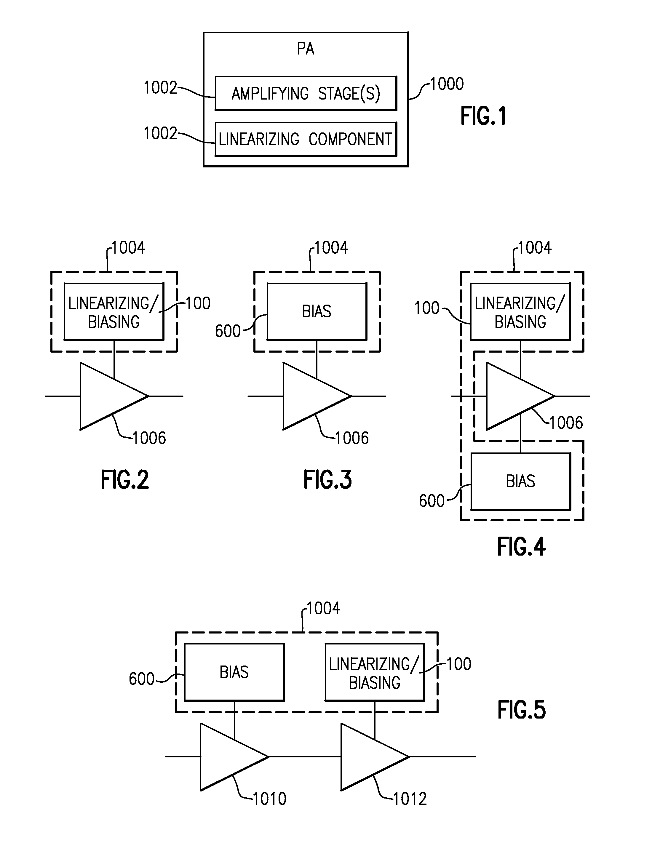
[0061]FIG. 1 shows a power amplifier (PA) assembly 1000 having one or more amplifying stages 1002 and a linearizing component 1004. As described herein such a linearizing component can provide improved linearity performance for some or all of the amplifying stage(s) 1002.

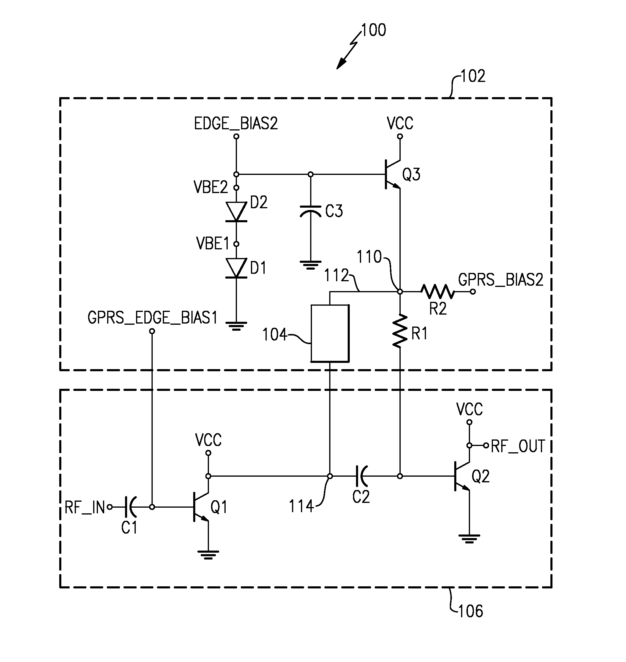
[0062]FIGS. 2-4 depict the one or more amplifying stages 1002 collectively as 1006. FIG. 2 shows that in some embodiments, the linearizing component 1004 of FIG. 1 can include a linearizing / biasing circuit 100 having one or more features described herein. Such a linearizing / biasing circuit can provide desirable linearizing functionality to some or all of the amplifying stages 1006. Various examples related to the linearizing / biasing circuit 100 of FIG. 2 are described herein in reference to FIGS. 6-16.

[0063]FIG. 3 shows that in some embodiments, the linearizing...


PUM


Abstract

Improved linearity performance for multi-mode power amplifiers. A power amplifier (PA) assembly can include a radio-frequency (RF) amplification path having a first stage and a second stage, with each stage including a transistor. The PA assembly can further include a biasing circuit having a first bias path between a supply node and the base of a corresponding transistor. The PA assembly can further include a linearizing circuit implemented as either or both of a second bias path and a coupling path relative to the first bias path. The second bias path can be configured to provide an additional base bias current to the base under a selected condition. The coupling path can be configured to improve linearity of the corresponding transistor operating in a first mode while allowing a ballast resistance to be sufficiently robust for the corresponding transistor operating in a second mode.

Description

CROSS-REFERENCE TO RELATED APPLICATION(S)[0001]This application claims priority to U.S. Provisional Application No. 61 / 901,057 filed Nov. 7, 2013, entitled SYSTEMS, CIRCUITS AND METHODS RELATED TO MULTI-MODE POWER AMPLIFIERS HAVING IMPROVED LINEARITY, and U.S. Provisional Application No. 62 / 004,141 filed May 28, 2014, entitled CIRCUITS AND METHODS RELATED TO POWER AMPLIFIER BIAS CIRCUITS HAVING PARALLEL EMITTER FOLLOWERS, the disclosure of each of which is hereby expressly incorporated by reference herein in its entirety.BACKGROUND[0002]1. Field[0003]The present disclosure generally relates to multi-mode power amplifiers having improved linearity.[0004]2. Description of the Related Art[0005]In wireless communication applications, size, cost, and performance are examples of factors that can be important for a given product. For example, to reduce both of the cost and product size, wireless components such as multi-mode and multi band power amplifiers are becoming more popular. In an ...

Claims


Application Information

Patent Timeline
Patent Type & Authority Patents(United States)
IPC IPC(8): H03F1/32H03F3/21H03F3/193H03F3/195H03F3/191H03F3/24
CPCH03F1/32H03F3/191H03F3/195H03F3/211H03F3/245H03F2200/18H03F2200/451H03F2201/3215H03F2203/21127H03F2203/21145H03F3/19
Inventor NI, JIANXINGGERARD, MICHAEL LYNNBAIRAVASUBRAMANIAN, RAMANANROWLAND, DWAYNE ALLENBANOWETZ, MATTHEW LEE
Owner SKYWORKS SOLUTIONS INC
Why Eureka
Try Eureka