
Method for digital error correction for binary successive approximation analog-to-digital converter (ADC)

a digital error correction and binary successive approximation technology, applied in the field of analog-to-digital converters (adcs), can solve the problems of meta-stability problems, heavy and time-wasting modifications of the original topology by the designer, and almost always generic redundancy techniques known in the ar

Active Publication Date: 2016-10-18
STMICROELECTRONICS INT NV
View PDF4 Cites 3 Cited by
  • Summary
  • Abstract
  • Description
  • Claims
  • Application Information

AI Technical Summary

Benefits of technology

The patent describes a method for correcting decision errors in a N+1 bits Successive Approximation Register (SAR) analog-to-digital converter. The method involves generating two binary codes, carrying out binary decision processing on them using the SAR method, and comparing the results with the input voltage. The method also includes assigning weights to the bits of the binary codes and using a constant term to generate the final digital output code. The technical effect of this method is to improve the accuracy of the analog-to-digital conversion process and reduce errors in the final output code.

Problems solved by technology

However, the redundancy techniques known in the art are almost always generic, e.g., they are not linked to any particular A / D converter topology.
As a consequence, applying a known redundancy technique to an existing SAR A / D converter would require for the designer heavy and time-wasting modifications on the original topology and layout of the converter itself.
In addition, contrary to a conventional SAR algorithm, the redundancy techniques known in the art require additional processing to be performed by the digital controller of the converter during the conversion to determine a correct code to be compared.
This can lead to meta-stability problems, whose aftermaths are not always easy to foresee and minimize.

Method used


Image

  • Method for digital error correction for binary successive approximation analog-to-digital converter (ADC)
  • Method for digital error correction for binary successive approximation analog-to-digital converter (ADC)
  • Method for digital error correction for binary successive approximation analog-to-digital converter (ADC)

Examples


Embodiment Construction

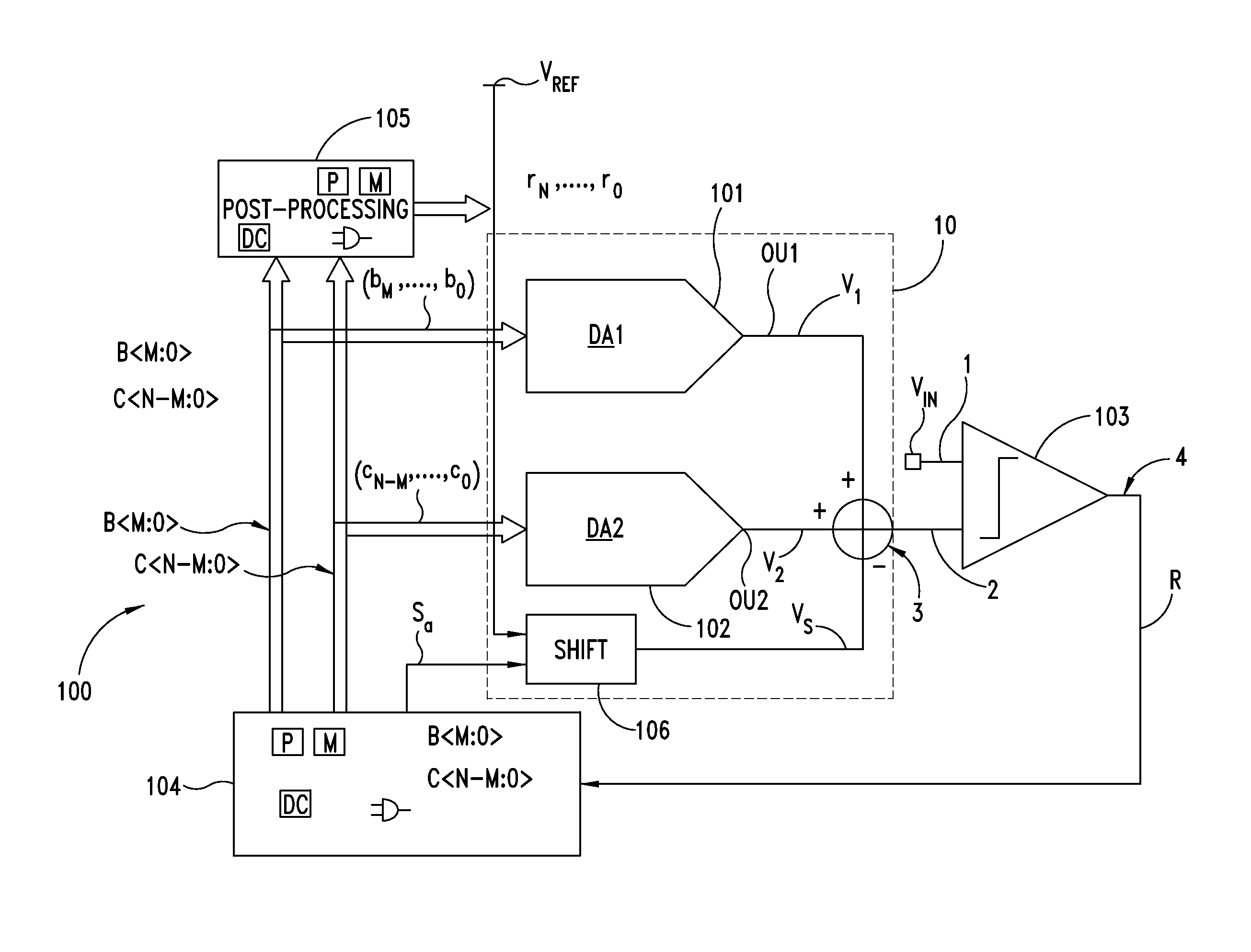
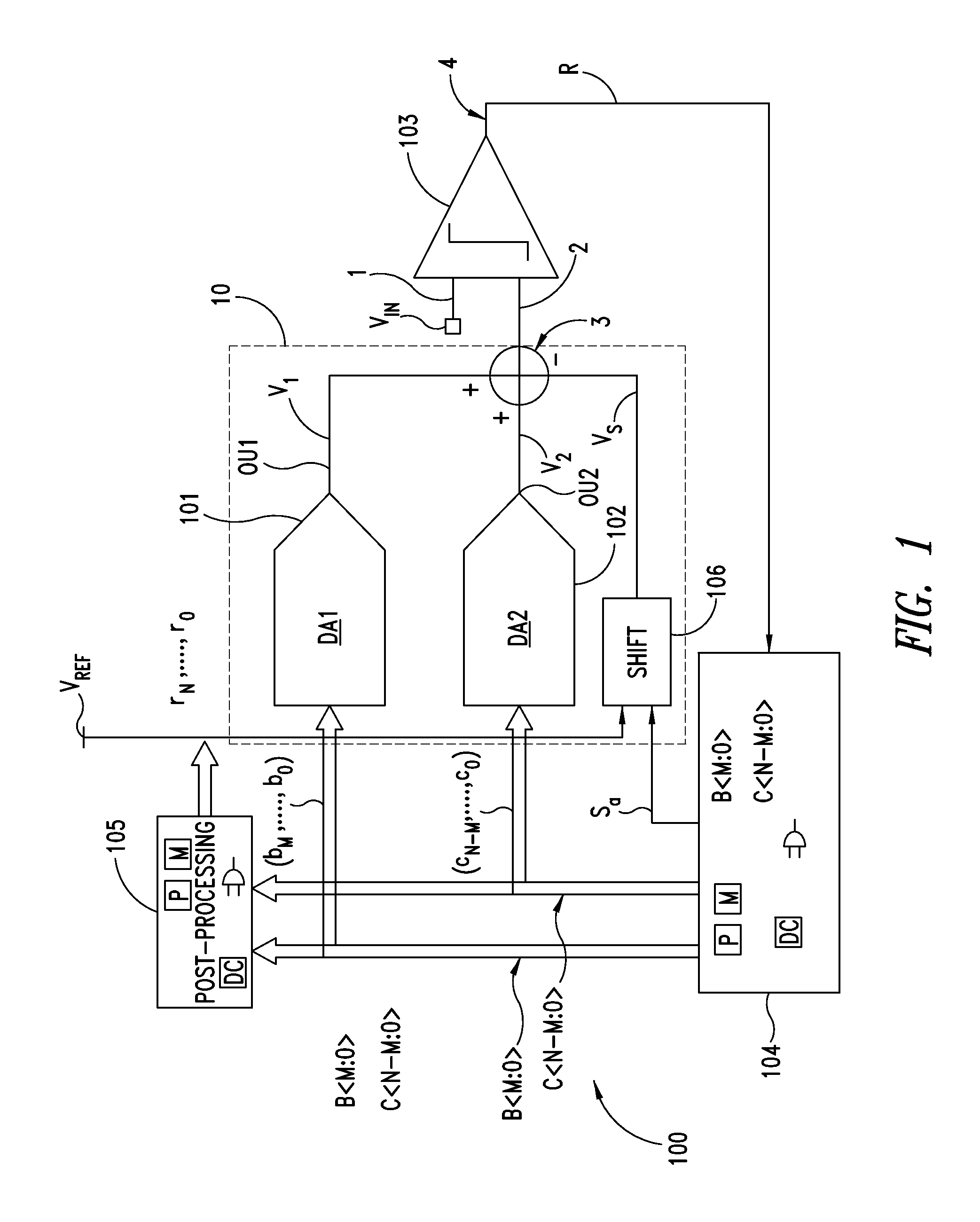
[0039]With reference to FIG. 1, a functional block structure of an N+1 bit Successive Approximation Register (SAR) analog-to-digital (A / D) converter implementing an embodiment of a method is indicated with the reference number 100. In the following, the SAR analog-to-digital converter 100 is also indicated, simply, as A / D converter.

[0040]Such A / D converter 100 can be used in many electronic applications wherein a conversion of analog voltage signals from the analog domain to the digital domain is required, for example in portable communication apparatuses, such as mobile phones, smart-phones or tablets.

[0041]Particularly, with reference to FIG. 1, the A / D converter 100 comprises a digital-to-analog conversion module or converter 10 which comprises a first 101 and a second 102 digital-to-analog (DA1, DA2) conversion block.

[0042]In addition, the A / D converter 100 comprises a register and control logic unit 104 configured to generate a first binary code bM, bM−1, . . . , b0 including M...


PUM


Abstract

An analog input voltage is converted to a digital code by, generating a first set of confirmed bits based on a first series of comparisons of an output of a digital-to-analog converter with the analog input voltage and generating a second set of confirmed bits based on a second series of comparisons of the output of the digital-to-analog converter with the analog input voltage. The first set of confirmed bits is independent of the second series of comparisons. The bits of the digital output code corresponding to the analog input voltage are generated based on the first set of confirmed bits, the second set of confirmed bits and a constant value representative of a voltage shift introduced in the digital-to-analog converter between the first series of comparisons and the second series of comparisons.

Description

BACKGROUND[0001]1. Technical Field[0002]The present disclosure relates to the field of Analog-to-Digital Converters (ADCs).[0003]2. Description of the Related Art[0004]In many electronic applications, a measure of analog signals is required. Usually, a General-Purpose Analog-to-Digital Converter or GPADC is used to convert such analog signals from the analog domain to the digital domain while measuring them. One of these electronic applications is, for example, mobile phones wherein many analog signals have to be continuously monitored to keep the microprocessor of the mobile phone device aware of the state of the device itself.[0005]Particularly, analog-to-digital (A / D) converters with Successive Approximation Register (SAR) charge redistribution are widely used for such applications.[0006]Even if SAR A / D converters have usually good performances in terms of conversion speed, in many applications is nowadays often desirable that such converters have also a resolution of 12 or up to...

Claims


Application Information

Patent Timeline
Patent Type & Authority Patents(United States)
IPC IPC(8): H03M1/66H03M1/00H03M1/46H03M1/06H03M1/08H03M1/68H03M1/80H03M1/76
CPCH03M1/46H03M1/001H03M1/069H03M1/0845H03M1/687H03M1/468H03M1/765H03M1/804H03M1/0617H03M1/1071H03M1/124
Inventor GIRARDI, FRANCESCAMINUTI, ALBERTONICOLLINI, GERMANOZAMPROGNO, MARCO
Owner STMICROELECTRONICS INT NV
Learn More