
Optical non-uniformity correction (NUC) for active mode imaging sensors

a technology of non-uniformity correction and active mode imaging, which is applied in the field of optical non-uniformity correction (nuc) for active mode imaging sensors, can solve the problems of non-uniform imaging sensor non-uniformity that must be corrected, high noise of fixed pattern, so as to improve the snr in the nuc'd image and limit noise scaling

Active Publication Date: 2016-10-18
RAYTHEON CO
View PDF8 Cites 17 Cited by
  • Summary
  • Abstract
  • Description
  • Claims
  • Application Information

AI Technical Summary

Benefits of technology

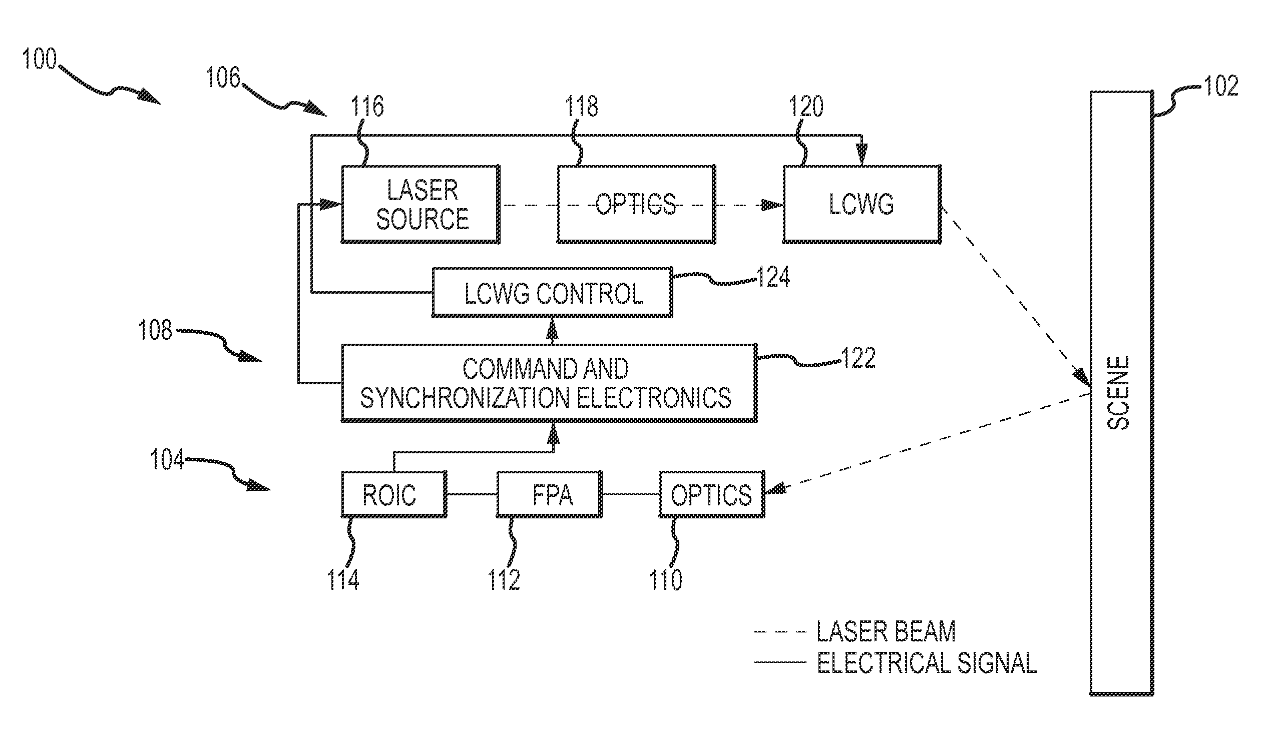
[0013]In an embodiment, the laser spot is scanned over the portion of the FOV within a frame time. The pixelated imager detects the laser spot's reflected energy of that portion of a scene, which is read out each frame time. The scanned laser spot simultaneously performs the NUC and provides the illumination of the FOV for imaging the scene. As a result, visibility of the scene is not lost during NUC and an additional black body source is not required for NUC. By limiting noise scaling, optical NUC improves the SNR in the NUC'd image.

Problems solved by technology

However, due to manufacturing issues of the pixelated imager, environmental variations and the radiometry of point sources, there are non-uniformities that exist in imaging sensors that must be corrected.
Notwithstanding the name, the fixed pattern noise can change with time and operating conditions such as temperature.
Without correction, the sensor response will be highly non-uniform over the FOV, particularly if the LOS angle is appreciable.
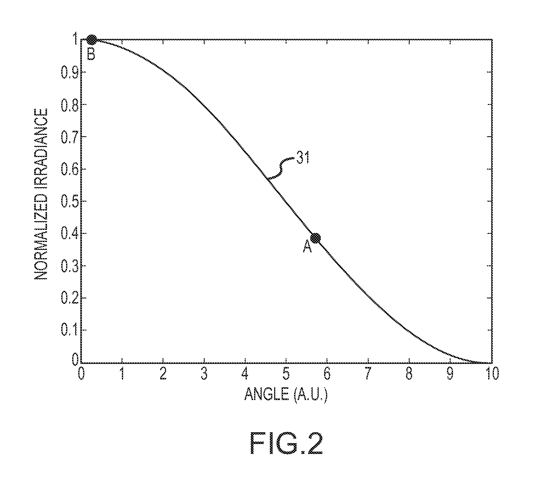
This accounts for both fixed pattern noise and angle of incidence roll off over the FOV.
An undesirable effect is scaling (increasing) the noise.
This process is computationally demanding and uses statistics to determine the non-uniformity of the scene, which could introduce errors in the final image.

Method used


Image

  • Optical non-uniformity correction (NUC) for active mode imaging sensors
  • Optical non-uniformity correction (NUC) for active mode imaging sensors
  • Optical non-uniformity correction (NUC) for active mode imaging sensors

Examples


Embodiment Construction

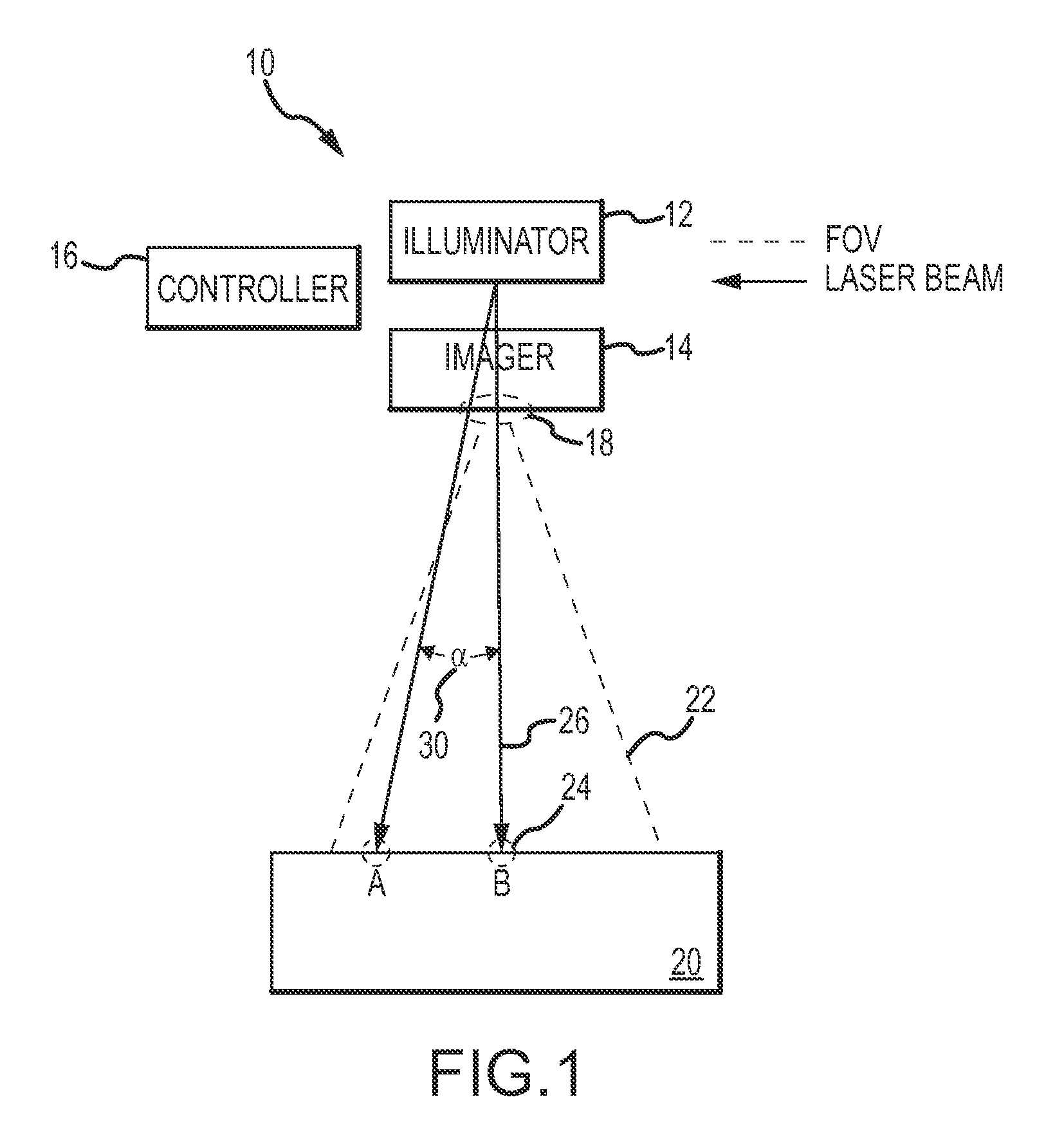
[0028]An optical non-uniformity correction (NUC) of an active mode sensor scans a spot over a portion of the sensor's FOV within a frame time so that the net response of the sensor is approximately uniform. Scanning the laser spot simultaneously performs the NUC and provides the illumination of the FOV for imaging the scene. The response of the sensor's imager will fall off with an increasing angle of incidence. In some cases, the illuminated portion of the scene will form a Lambertian point source whose illuminations rolls off as the 4th power of the cosine of the angle of incidence. The angle of incidence may include a variable line-of-sight (LOS) component from the imager to the scene and a fixed FOV component across the scene within the FOV. The laser spot is suitably scanned in an overlapping geometrical pattern relative to a line-of-sight of the sensor's imager while modulating a spacing between overlapping laser spots, the size of the spot, a dwell time of the laser spot or t...


PUM


Abstract

Optical non-uniformity correction (NUC) of an active mode image sensor scans a spot over a portion of the sensor's FOV within a frame time so that the net response of the sensor is approximately uniform. Scanning the laser spot simultaneously performs the NUC and provides the illumination of the FOV for imaging the scene. The laser spot is suitably scanned in an overlapping geometrical pattern relative to a line-of-sight of the sensor's imager while modulating a spacing between overlapping laser spots, the size of the spot, a dwell time of the laser spot or the energy of the laser spot or combinations thereof as a function of the scan position of the laser spot so that the laser illumination is inversely proportional to the imager response at the scan position of the laser spot. A liquid crystal waveguide may be used to form and scan the small laser spot over the FOV within the frame time.

Description

BACKGROUND OF THE INVENTION[0001]1. Field of the Invention[0002]This invention relates to optical non-uniformity correction (NUC) for active mode imaging sensors, and more particularly to optical NUC for angle of incidence between the scene and imager.[0003]2. Description of the Related Art[0004]Imaging sensors typically include a pixelated imager that is sensitive to incident photons within a certain spectral band e.g. Near IR (NIR), Short Wave IR (SWIR), Mid Wave IR (MWIR), Long Wave IR (LWIR), visible etc., imaging optics having an entrance pupil for receiving light from a scene within a field-of-view (FOV) of the sensor and imaging the FOV onto the imager, and a read out circuit for reading out an image of the FOV within the spectral band at a frame rate. The scene is composed of multiple point sources of light (collimated due to the distance to the scene) at different angles of incidence. The optics focus light from each point source onto the pixelated imager with the angle of ...

Claims


Application Information

Patent Timeline
Patent Type & Authority Patents(United States)
IPC IPC(8): A62B1/04H04N17/00
CPCH04N17/002A62B1/04H04N25/63H04N23/56
Inventor UYENO, GERALD P.KELLER, SEAN D.ACTON, DAVID D.
Owner RAYTHEON CO
Learn More