Medical manipulator

a technology of manipulators and end-effectors, which is applied in the field of medical manipulators, can solve the problems that the medical manipulator itself cannot be used, and achieve the effects of improving manipulation, suppressing the influence of weight increase, and reliably and simply operating the end-effector

Active Publication Date: 2016-10-25
KARL STORZ GMBH & CO KG
View PDF22 Cites 262 Cited by
  • Summary
  • Abstract
  • Description
  • Claims
  • Application Information

AI Technical Summary

Benefits of technology

[0006]The present invention is made in light of the problem, and an object of the present invention is to provide a medical manipulator that can suppress influence of the weight increase caused by the mounting of the driving source, and that, depending on the situation, can be used by only a manual manipulation without relying on the driving source.
[0018]In the medical manipulator, the unit-side manipulation portions may be provided in side portions of the drive unit. In a state where the drive unit is mounted on the handle, the unit-side manipulation portions may be positioned to overlap with the manual manipulation portion in a forward and backward direction. According to the configuration, before and after the drive unit is mounted on the handle, a manipulation position of the manual manipulation portion remains almost unchanged, and manipulability is improved.
[0019]In the medical manipulator according to the present invention, when the drive unit is mounted on the handle for use of the medical manipulator, it is possible to reliably and simply operate the end effector even with a small manipulating force. When a drive of the driving source is not necessary, it is possible to detach the drive unit from the handle and to make the medical manipulator light. Furthermore, even in a case where any problem occurs on the side of the drive unit during an operation, it is possible to continue to carry out the operation using only the surgical tool. That is, it is possible to suppress influence of the weight increase caused by the mounting of the driving source, and, depending on the situation, it is possible to use the medical manipulator by only a manual manipulation without relying on the driving source.

Problems solved by technology

In addition, in a case where the medical manipulator is configured to be continuously operated by the motor when the motor cannot be driven due to occurrence of an event, the medical manipulator itself cannot be used.

Method used


Image

  • Medical manipulator
  • Medical manipulator
  • Medical manipulator

Examples


first embodiment

[First Embodiment]

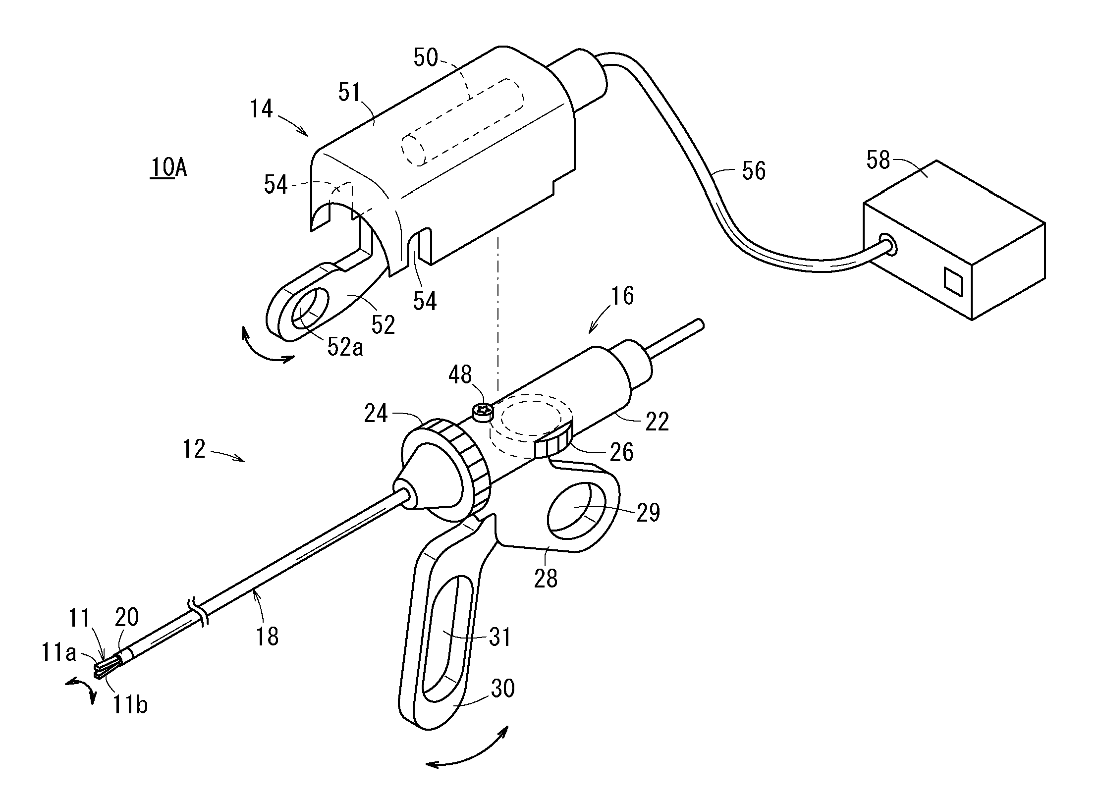
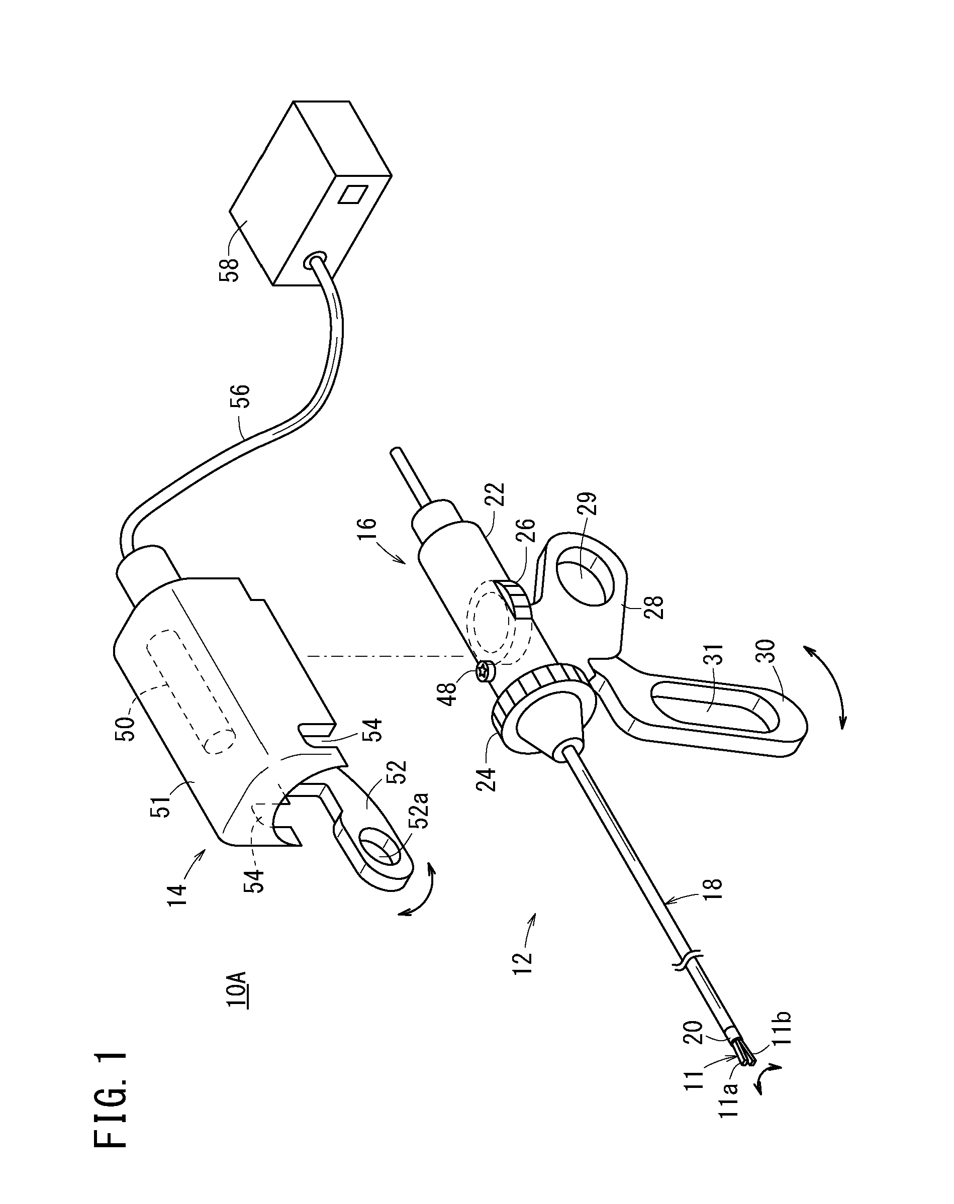
[0029]FIG. 1 is a perspective view of a medical manipulator 10A according to a first embodiment of the present invention. The medical manipulator 10A includes a surgical tool 12 that has an end effector 11 provided at the distal end and a drive unit 14 that is detachable from the surgical tool 12. The medical manipulator 10A is medical equipment that grasps a part of the living body or touches the living body using the end effector 11 provided at the distal end, and carries out a predetermined treatment. When the type of end effector 11 provided at the distal end is changed, the medical manipulator 10A can be configured to have grasping forceps, a needle driver, a monopolar radio knife, bipolar radio knife or the like.

[0030]The surgical tool 12 includes the end effector 11 that configures a distal portion of the surgical tool 12; a handle 16 that configures a proximal portion of the surgical tool 12 to drive the end effector 11; and a shaft (interlock portion) 18 t...

second embodiment

[Second Embodiment]

[0058]Subsequently, a medical manipulator 10B according to a second embodiment will be described with reference to FIG. 4. In the medical manipulator 10B according to the second embodiment, the same reference signs are assigned to elements that have the same or similar functions and effects to those of the elements of the medical manipulator 10A according to the first embodiment, and detailed description will be omitted. In addition, when the second embodiment is described below, with regard to configuration elements different from those of the first embodiment, “a” is added to the sign (numeral) assigned to each of the configuration elements of the first embodiment.

[0059]In a surgical tool 12a of the medical manipulator 10B according to the second embodiment, a handle 16a, particularly, an internal mechanism of a body portion 22a and a main unit body 51a are different from the internal mechanism of the body portion 22 of the surgical tool 12 and the main unit bod...

third embodiment

[Third Embodiment]

[0070]The handle 16 (16a) may be provided with a clutch mechanism (switching mechanism) in such a manner that both of a rolling operation and a tilting operation can be carried out by the one motor 50. In this case, in a state where the drive unit 14 is mounted on the handle 16 (16a), the clutch mechanism is configured to selectively switch a switching state between a first switching state where a power transmission path is formed between the motor 50 and the rolling operation drive shaft 40 and a second switching state where a power transmission path is formed between the motor 50 and the tilting operation drive shaft 42. Hereinafter, a medical manipulator that includes the clutch mechanism according to a fourth embodiment will be described.

[0071]FIG. 6 illustrates a clutch mechanism (switching mechanism) 70 in a configuration example of a medical manipulator 10C according to the Third embodiment. In FIG. 6, the same signs are assigned to the same configuration el...


PUM


Abstract

A medical manipulator includes a surgical tool that has an end effector at a distal end and a drive unit that is detachable from a handle of the surgical tool. In a state where the drive unit is mounted on the handle, when a manipulation lever is manipulated, a driving force of a motor is transmitted to the handle, and the end effector is operated. Even in a state where the drive unit is detached from the handle, the surgical tool can be independently used by a manual manipulation.

Description

TECHNICAL FIELD[0001]The present invention relates to a medical manipulator that is used when a surgical operation, particularly, an endoscopic surgical operation is carried out, and that can be operated based on a manual manipulation or based on a drive of a driving source.BACKGROUND ART[0002]In an endoscopic surgical operation (or, referred to as a laparoscopic surgical operation), a plurality of holes are punctured in the abdomen of a patient, trocars (tubular instruments) are inserted through the holes, and a laparoscope (camera) and a plurality of forceps are inserted into the coelom via each of the trocars. A gripper, scissors, a blade of a radio knife or the like for grasping the biological tissue or the like is attached to distal portions of the forceps as an end effector.[0003]After the laparoscope and the forceps are inserted into the coelom, an operation is carried out by operating the forceps while observing intra-abdominal conditions displayed on a monitor that is conne...

Claims


Application Information

Patent Timeline
Patent Type & Authority Patents(United States)
IPC IPC(8): A61B17/00A61B17/29
CPCA61B17/00234A61B17/29A61B17/2909A61B34/70A61B2017/0046A61B2017/00398A61B2017/00734A61B2017/2927A61B2017/2929
Inventor ISHIDA, SHINJISANO, HIROAKIISHIHARA, KAZUHITOKITAMURA, KEIKOHIYAMA, YOSHIO
Owner KARL STORZ GMBH & CO KG
Why Eureka
Try Eureka