Ink wiping system of an intaglio printing press and intaglio printing press comprising the same

a technology of ink wiping system and ink cartridge, which is applied in the direction of printing presses, rotary presses, printing presses, etc., can solve the problems of time-consuming maintenance operations of the known ink wiping system, substantial mechanical constraints on the overall construction of the ink wiping system, and the roller assembly which is supported on the wiping tank subject to considerable mechanical constraints, etc., to facilitate maintenance operations and compact configuration

Active Publication Date: 2016-10-25
KBA NOTASYS SA
View PDF75 Cites 1 Cited by
  • Summary
  • Abstract
  • Description
  • Claims
  • Application Information

AI Technical Summary

Benefits of technology

[0019]A further aim of the invention is to provide such an ink wiping system that facilitates maintenance operations, in particular cleaning of the ink wiping system.
[0020]Yet another aim of the invention is to provide such an ink wiping system that allows an easy and quick exchange of a used wiping roller assembly by a new wiping roller assembly.
[0023]Such an ink wiping system greatly facilitates maintenance operations in that the wiping roller assembly can simply be retracted to the parking position by means of the wiping roller retracting device, thereby freeing and allowing full access to the wiping tank for cleaning purposes. Once the cleaning operations have been completed, the wiping roller assembly can be moved back to its working position.
[0024]The storage section can advantageously be located immediately below the wiping tank, which ensures a very compact configuration and allows unobstructed access to the wiping tank.
[0028]Such an ink wiping system likewise greatly facilitates maintenance operations in that a used wiping roller assembly can simply be transferred onto a trolley coupled to the interlocking mating guide, while a new wiping roller assembly can be transferred from a trolley coupled to the interlocking mating guide to the working position. It will become apparent from the following description that one and a same trolley can be used to transport the new wiping roller assembly to the ink wiping system and evacuate the used wiping roller assembly, in which case the aforementioned storage section can be exploited as temporary storage area (see illustrations of FIGS. 5A to 5J). In another embodiment, a trolley can be used to evacuate the used wiping roller assembly, and the same trolley (once freed from the used wiping roller assembly) or another empty trolley can be used to transport a new wiping roller assembly to the ink wiping system (see illustrations of FIGS. 4A to 4L).
[0032]In yet another advantageous embodiment, the wiping tank can be fixedly secured to a machine frame of the intaglio printing press and be unable to move with respect to the machine frame, which solution allows for a highly robust ink wiping system configuration.

Problems solved by technology

Maintenance operations of the known ink wiping systems are time-consuming as the wiping roller assembly is a relatively heavy component to manipulate, which typically necessitates the use of a crane to remove the wiping roller assembly from the wiping tank as already mentioned.
This substantially complicates the overall construction of the ink wiping system and the coupling thereof to the corresponding wiping solution supply and treatment system.
This further requires a robust and stable interlocking mechanism to properly secure the wiping tank onto the machine frame during printing operations, which requirement is exacerbated by the fact that the wiping roller assembly which is supported on the wiping tank is subjected to considerable mechanical constraints during printing operations.

Method used


Image

  • Ink wiping system of an intaglio printing press and intaglio printing press comprising the same
  • Ink wiping system of an intaglio printing press and intaglio printing press comprising the same
  • Ink wiping system of an intaglio printing press and intaglio printing press comprising the same

Examples


Embodiment Construction

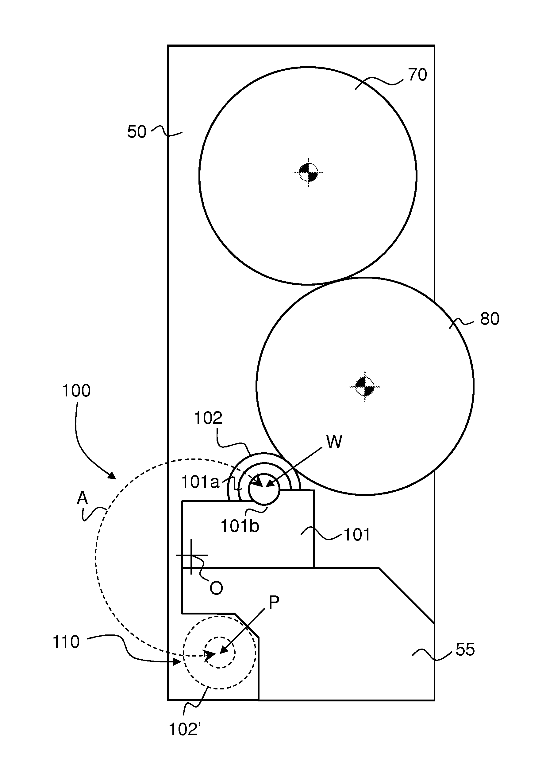
[0041]Within the scope of the present invention, the expression “intaglio printing cylinder” designates either a cylinder whose surface is provided with intaglio patterns engraved directly onto the circumference of the cylinder or a plate cylinder carrying on its circumference at least one intaglio printing plate with engraved intaglio patterns (the second solution being now more common in the art). In the following description, it will be assumed for the sake of illustration that the intaglio printing cylinder is a plate cylinder carrying several intaglio printing plates on its circumference.

[0042]FIG. 3 is a schematic partial side view of an ink wiping system according to a first aspect of the invention. In FIG. 3, reference numeral 50 designates one of a pair of side frames supporting the impression cylinder 70 and intaglio printing cylinder 80, while reference numeral 55 designates a wiping tank support supporting the wiping tank 101 of the ink wiping system 100. The side frames...


PUM


Abstract

There is described an ink wiping system (100; 100′; 100″) of an intaglio printing press comprising a wiping tank (101) and a rotatable wiping roller assembly (102; 102*) supported on and partly located in the wiping tank (101) for wiping excess ink from the surface of a rotatable intaglio printing cylinder (80) of the intaglio printing press. The ink wiping system (100; 100′; 100″) comprises a wiping roller retracting device (150) which forms an integral part of the ink wiping system (100; 100′; 100″) and is adapted to be coupled to the wiping roller assembly (102; 102*) to move the wiping roller assembly (102; 102*) between a working position (W) where the wiping roller assembly (102; 102*) is supported on and partly located in the wiping tank (101) for cooperation with the intaglio printing cylinder (80) and a parking position (P) where the wiping roller assembly (102; 102*) is retracted out of the wiping tank (101) and away from the intaglio printing cylinder (80). In the working position (W) of the wiping roller assembly (102; 102*), the wiping roller retracting device (150) is coupled to the wiping roller assembly (102; 102*). The ink wiping system (100; 100′; 100″) further includes, at the parking position (P), a storage section (110) adapted to receive the wiping roller assembly (102; 102*) which is retracted by the wiping roller retracting device (150).

Description

[0001]This application is the U.S. national phase of International Application No. PCT / IB2013 / 051920, filed 11 Mar. 2013, which designated the U.S. and claims priority to EP Application No. 12158948.5, filed 9 Mar. 2012, the entire contents of each of which are hereby incorporated by reference.TECHNICAL FIELD[0002]The present invention generally relates to the wiping of rotatable intaglio printing cylinders of intaglio printing presses. More precisely, the present invention relates to an ink wiping system of an intaglio printing press and to an intaglio printing press comprising the same.BACKGROUND OF THE INVENTION[0003]Intaglio printing presses are widely used in security printing for printing security documents, especially banknotes. Prior art intaglio printing presses are for instance disclosed in Swiss Patent No. CH 477 293 A5, European Patent Applications Nos. EP 0 091 709 A1, EP 0 406 157 A1, EP 0 415 881 A2, EP 0 563 007 A1, EP 0 873 866 A1, EP 1 602 483 A1, and International...

Claims


Application Information

Patent Timeline
Patent Type & Authority Patents(United States)
IPC IPC(8): B41F9/08B41F9/16B41F31/07B41F9/10B41F31/30
CPCB41F9/16B41F9/1018B41F31/07B41F31/308B41F9/10
Inventor SCHARKUS, VOLKERSOKOL, RALF HARALDSCHWITZKY, VOLKMAR ROLFCLAUDE, LAURENTWURSCH, ALAINSCHAEDE, JOHANNES GEORG
Owner KBA NOTASYS SA
Why Eureka
Try Eureka