Eureka AIR delivers breakthrough ideas for toughest innovation challenges, trusted by R&D personnel around the world.

Female terminal

a terminal and female technology, applied in the field of female terminals, can solve the problems of increased insertion load and wear of the contact part between the male terminal and the female terminal, and achieve the effects of reducing insertion resistance, reducing wear of the contact part, and avoiding friction resistan

Active Publication Date: 2016-11-01
YAZAKI CORP
View PDF19 Cites 10 Cited by
  • Summary
  • Abstract
  • Description
  • Claims
  • Application Information

AI Technical Summary

Benefits of technology

[0019]According to the female terminal having the structure as described above in item (1), the inner diameter of the diameter variable part of the tubular contact member is set to be larger than the outer diameter of the male terminal which is inserted into the contact member. Therefore, it is possible to insert the male terminal into the tubular contact member of the female terminal, while securing a gap with respect to the contact member. Consequently, the male terminal can be inserted into the female terminal with almost no friction resistance with respect to the contact member, and it is possible to reduce an insertion resistance, and also to reduce a wear of the contact part. Moreover, the diameter variable part of the contact member can be reduced in diameter, by rotating the rotary ring after the male terminal is inserted, and by twisting the other holding ring of the contact member with respect to the one holding ring. As the results, it is possible to bring the inner periphery of the diameter variable part into pressure contact with the outer periphery of the male terminal, thereby to establish electrically stabilized connection between the female terminal and the male terminal.
[0020]According to the female terminal having the structure as described above in item (2), by twisting the holding rings at the both ends relatively to each other, it is possible to position a plurality of the metal wires on the hyperboloid, and hence, a number of the metal wires can be brought into pressure contact with the outer periphery of the male terminal at the smallest inner diameter position of the hyperboloid. Therefore, a number of contact points (contact points between the metal wires and the male terminal) are present along an entire circumference. As the results, a stabilized contact state can be obtained between the male terminal and the female terminal, and a temperature rise of the contact part can be reduced. Further, because a curved degree of the hyperboloid can be varied according to a twisting angle, contact loads of the metal wires with respect to the male terminal can be varied, and therefore, it is possible to easily manage the contact resistance.
[0021]According to the female terminal having the structure as described above in item (3), it is possible to stably maintain the electrically connected state between the male terminal and the female terminal.
[0022]According to the female terminal having the structure as described above in item (4), it is possible to stably maintain the electrically connected state between the male terminal and the female terminal employing a simple structure.
[0023]According to the invention, when the male terminal is inserted into the tubular contact member which constitutes the female terminal, a gap can be secured between the contact member and the male terminal, and thus, the friction resistance at a time of insertion can be reduced. Therefore, the insertion load can be reduced, and wear of the contact part can be also reduced. Moreover, by simply rotating the rotary ring after the male terminal is inserted, it is possible to reduce the diameter of the diameter variable part of the contact member, thereby to bring the contact member into pressure contact with the male terminal In this manner, it is possible to electrically connect the female terminal with the male terminal.

Problems solved by technology

Accordingly, there is such a problem that the spring load causes a friction resistance, and an insertion load is increased.
Moreover, there is another problem that a contact part between the male terminal and the female terminal tends to wear, because the male terminal is inserted while being subjected to the friction resistance.

Method used


Image

  • Female terminal
  • Female terminal
  • Female terminal

Examples


Embodiment Construction

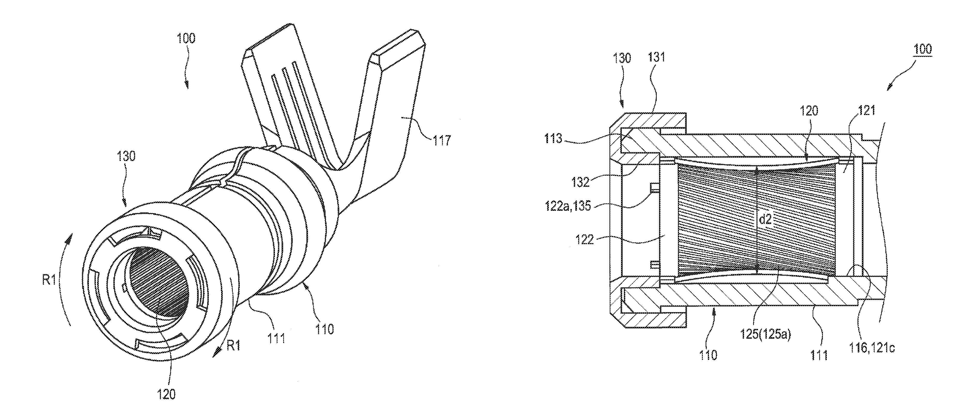
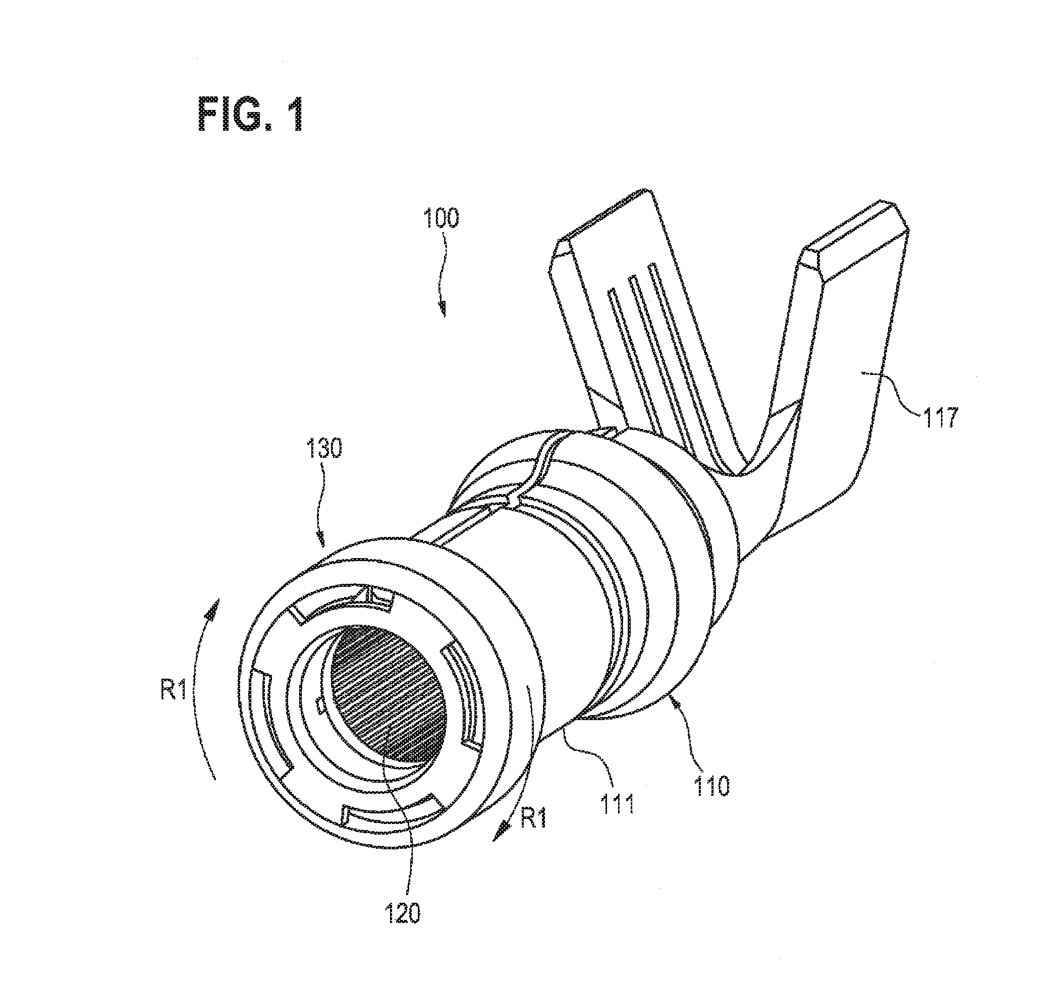
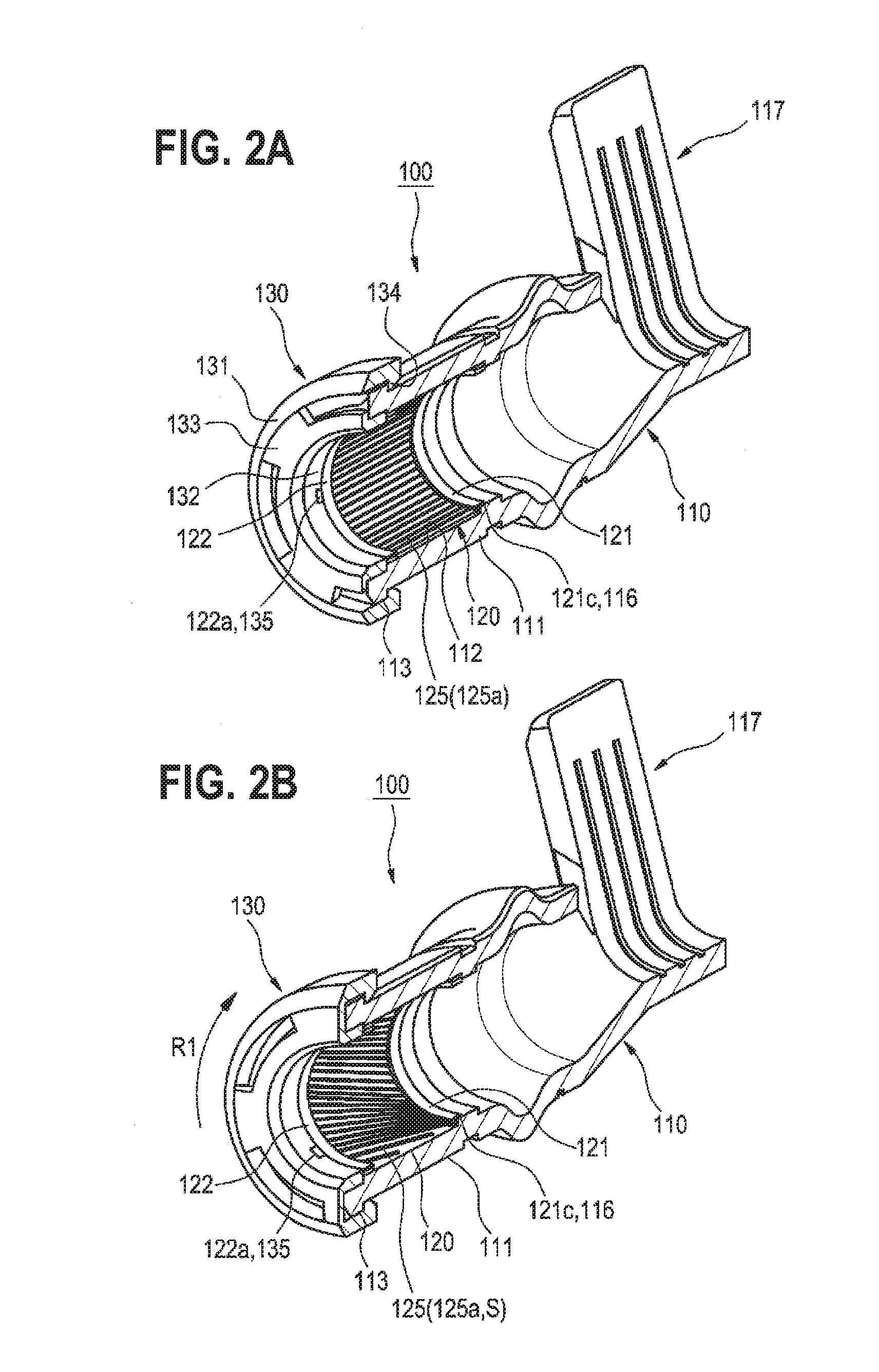
[0035]An embodiment according to the invention will be described below, referring to the drawings.

[0036]FIG. 1 is a perspective view showing a structure of a female terminal in the embodiment, FIGS. 2A and 2B are perspective views showing the female terminal in a state divided into halves along a sectional plane in a longitudinal direction, FIGS. 3A and 3B are perspective views showing a structure of the contact member which is used in the female terminal, FIGS. 4A and 4B are sectional side views of the female terminal, FIG. 5 is a side view showing a structure of a distal end part of a male terminal to be engaged with the female terminal, FIGS. 6A and 6B are sectional side views showing a state where the male terminal is inserted into the female terminal, FIG. 7A is a perspective view showing a state before a rotary ring is fixed to a contact holder by means of a fixing mechanism, FIG. 7B is a perspective view showing a state after the rotary ring has been fixed to the contact hold...


PUM


Abstract

A female terminal includes a terminal body having a contact holder in a tubular shape at a front side of the terminal body, a contact member in a tubular shape which is contained inside the contact holder and into which a male terminal is inserted from a front side, and a rotary ring which is mounted to the contact holder. The contact member has a pair of holding rings provided at both ends thereof, and a diameter variable part held by a pair of the holding rings at both ends thereof, an inner diameter of the diameter variable part being set to be larger than an outer diameter of the male terminal in an initial state, and contracted to be smaller than the outer diameter of the male terminal, by twisting a pair of the holding rings.

Description

CROSS REFERENCE TO RELATED APPLICATIONS[0001]This application is a continuation of PCT application No. PCT / JP2014 / 065041, which was filed on Jun. 6, 2014 based on Japanese Patent Application (No. 2013-120964) filed on Jun. 7, 2013, the contents of which are incorporated herein by reference.BACKGROUND OF THE INVENTION[0002]1. Field of the Invention[0003]The present invention relates to a female terminal into which a pin-shaped male terminal is inserted from a front side.[0004]2. Description of the Related Art[0005]In Japanese Patent Publication No. 4209775, there is disclosed an example of a female terminal which is provided with a contact member having elasticity in a radial direction. As shown in FIGS. 9 and 10, this female terminal 10 has a cylindrical sleeve 20, and a cylindrical contact member 30 which is inserted into the sleeve 20. A plurality of engaging parts 21 are provided at an interval in a circumferential direction, at both ends in an axial direction of the cylindrical ...

Claims


Application Information

Patent Timeline
Patent Type & Authority Patents(United States)
IPC IPC(8): H01R13/62H01R4/18H01R13/187H01R13/213H01R101/00
CPCH01R4/183H01R13/187H01R13/213H01R2101/00
Inventor OHKUBO, YOSHITAKAANDO, SHUHEI
Owner YAZAKI CORP
Why Eureka
Eureka Blog
Learn More