System and method for pumping molten metal and melting metal scrap

a technology of molten metal and scrap, which is applied in the direction of lighting and heating apparatus, charge manipulation, furnaces, etc., can solve the problems of compromising the physical properties of metal articles, requiring a large amount of fuel by burners, and undesirable hydrogen gas in metals, so as to achieve the effect of improving the quality of molten metal processing and remarkable versatility

Active Publication Date: 2016-11-15
THUT BRUNO
View PDF9 Cites 15 Cited by
  • Summary
  • Abstract
  • Description
  • Claims
  • Application Information

AI Technical Summary

Benefits of technology

[0028]The present system advantageously enables the separating wall to remain in place. In one specific example feature, the scrap charging vessel can feed into the hearth. Thus, the present system can be put in place in a wide variety of existing furnaces with minimal modification to the furnace. It can provide circulation, scrap charging and transfer of molten metal, with or without gas treatment and with or without flux treatment, which offers a tremendous versatility, simplicity and improved quality of molten metal processing. Molten metal from the furnace can be formed into metal articles, for example in a die casting operation.

Problems solved by technology

The transfer function of the pump avoids a tapping operation which is dangerous and problematic.
A tremendous amount of fuel is required by the burners to heat and maintain the molten metal at a suitable temperature.
It is undesirable to have hydrogen gas in the metal.
Higher temperatures of molten aluminum lead to increased absorption of hydrogen gas and increased pin hole defects with resulting compromise in the physical properties of the metal articles.
Metal processing companies have expressed a reluctance in removing the separating wall because it is very labor intensive and costly to do so.

Method used


Image

  • System and method for pumping molten metal and melting metal scrap
  • System and method for pumping molten metal and melting metal scrap
  • System and method for pumping molten metal and melting metal scrap

Examples


Embodiment Construction

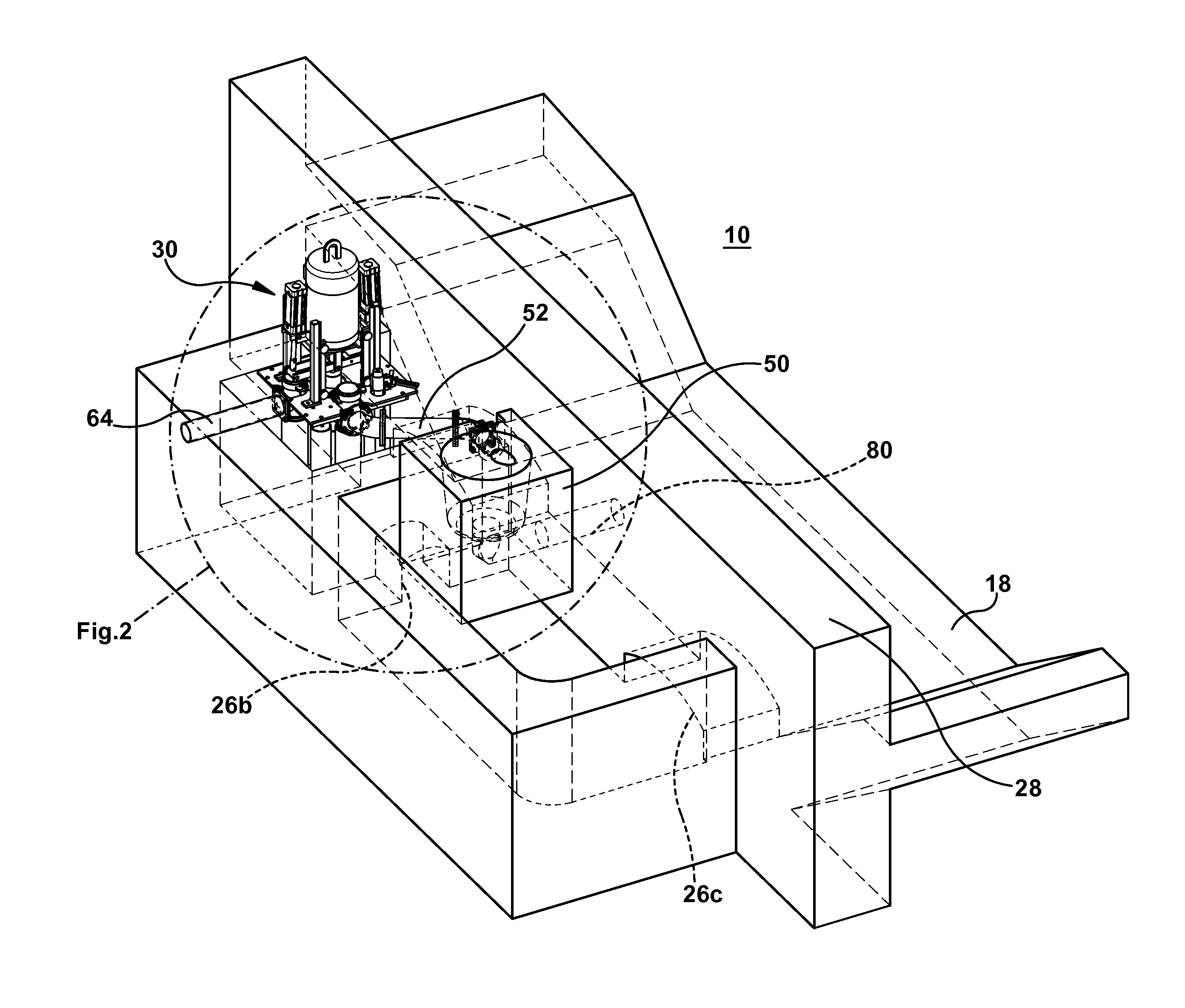
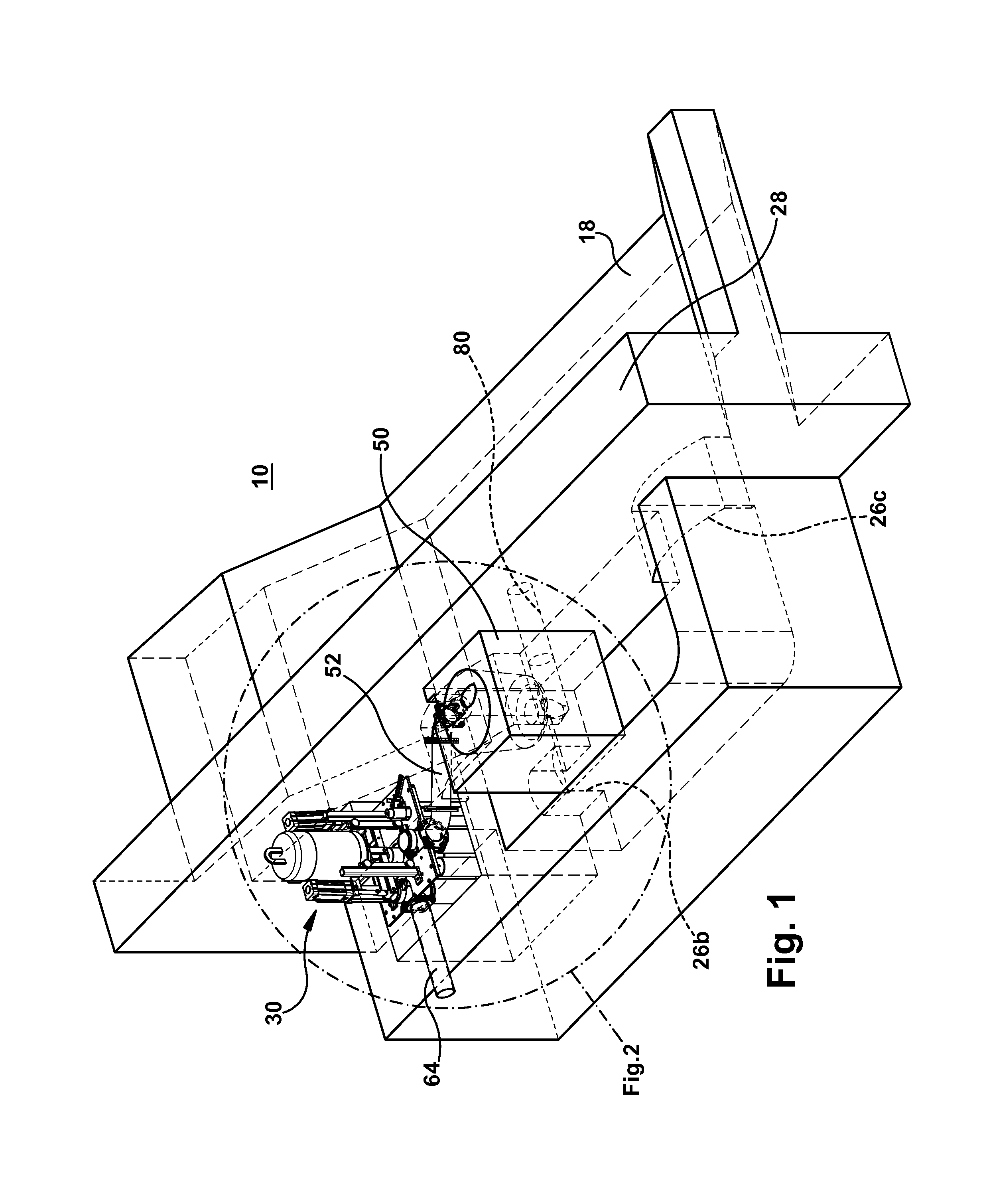
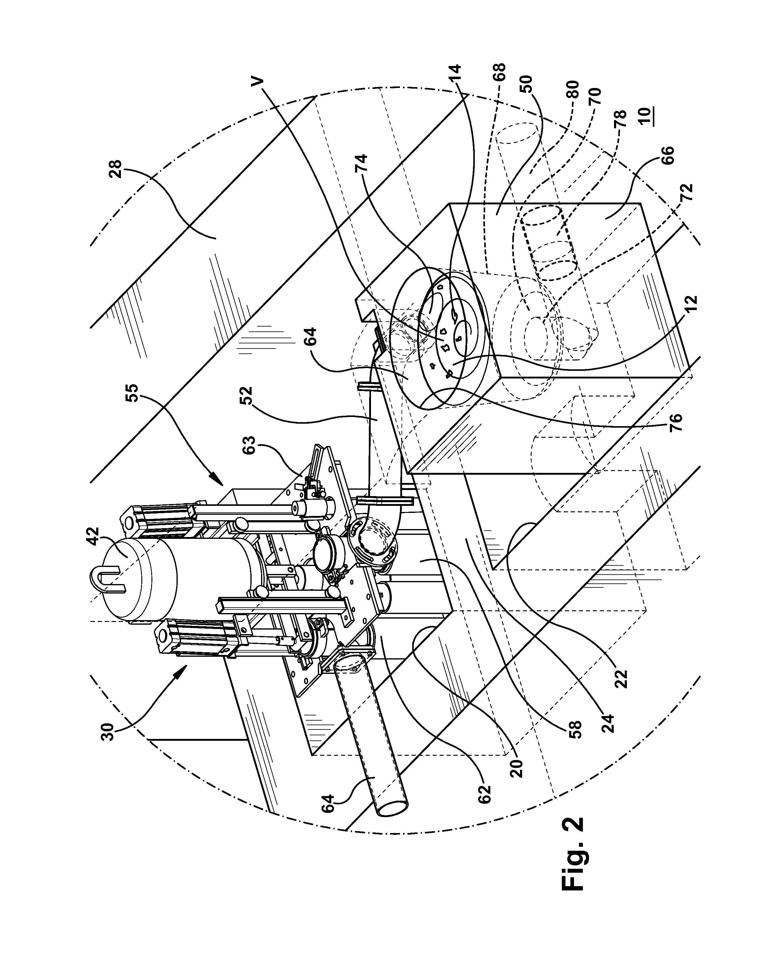
[0037]A system 10 of this disclosure is used to pump molten metal 12 and melt metal scrap 14 in a furnace 16. The furnace 16 is composed of refractory brick or block (referred to generally as refractory brick in this disclosure). Optional burners or other optional heating means (not shown) as known in the art are disposed in a main vessel 18 (e.g., a hearth). Ingots of metal can be melted in the hearth 18 or metal can be otherwise charged into the hearth. Outside the hearth 18 the furnace includes a first well 20 that is separated from a second well 22 by a refractory brick separating wall 24. The first well 20 and the second well 22 are in fluid communication with the hearth 18, though lower archways 26a, 26c in the walls between hearth and each well and lower archway 26b in the separating wall 24 between the first and second wells. These lower archways are below the molten metal level. In particular, in one example, the floor of the furnace forms a lower portion of the archway. Th...


PUM

PropertyMeasurementUnit
volumeaaaaaaaaaa
meltingaaaaaaaaaa
temperatureaaaaaaaaaa

Abstract

A system for pumping molten metal and melting metal scrap in a furnace that includes a first well that is separated from a second well by a refractory separating wall. The first well and the second well are in fluid communication with a main vessel, the separating wall including a passageway for molten metal. The system includes a pump disposed in the first well for pumping molten metal. A scrap charging vessel is disposed in the second well into which the scrap is added to molten metal contained therein. A conduit extends from the pump over the separating wall. Molten metal pumped from the pump travels from the conduit into the scrap charging vessel.

Description

FIELD OF THE INVENTION[0001]The present disclosure relates to pumps for pumping molten metal, in particular, to systems used for melting metal scrap.BACKGROUND OF THE INVENTION[0002]Pumps for pumping molten metal are used in furnaces in the production of metal articles. Common functions of pumps are circulation of molten metal in the furnace or transfer of molten metal to a remote location along risers that extend from a base of the pump connected to conduit that extends to the remote location. The transfer function of the pump avoids a tapping operation which is dangerous and problematic. The pump may be located in a separate, smaller chamber such as a pump well adjacent the main hearth.[0003]Currently, many metal die casting facilities employ a hearth containing a large proportion of the molten metal volume of the furnace. Solid ingots of metal may be periodically melted in the hearth. Metal scrap such as from aluminum cans is often charged into the molten metal in a scrap well ad...

Claims


Application Information

Patent Timeline
Patent Type & Authority Patents(United States)
IPC IPC(8): F27D3/14B22D41/00F27D3/00C22B9/16
CPCF27D3/14F27D3/0024F27D3/0025C22B9/16F27D2003/0054F27D27/005
Inventor THUT, BRUNO
Owner THUT BRUNO
Why Eureka
Try Eureka