Apparatus for measuring circular depolarization ratios in a weather radar

a technology of circular depolarization ratio and weather radar, which is applied in the field of apparatus for measuring circular depolarization ratio in weather radar, can solve the problems of low signal to noise ratio, lack of widespread use of operational applications, and the ldr mode of operation, so as to improve the accuracy of hydrometer detection, improve the accuracy of ldr data, and reliably extract ldr data

Active Publication Date: 2016-11-15
CLIMAVISION OPERATING LLC
View PDF16 Cites 2 Cited by
  • Summary
  • Abstract
  • Description
  • Claims
  • Application Information

AI Technical Summary

Benefits of technology

[0008]An apparatus and method for the pre and post processing of radar signals to allow for improved measuring of circular depolarization ratio data in a weather radar. The system uses a phase shifter, which is periodically calibrated to ensure proper polarity, to alter the transmission phase of one channel of a radar transmission output. Reflectivity signals are then processed in accordance with rules dependent upon the transmission phase shift to reliably extract circular depolarization ratio (“CDR”) data from the reflectivity signals. CDR data is used to enhance hydrometer recognition in a weather radar system.

Problems solved by technology

These variables are not practically measurable in an LDR mode of operation, and hence is one of the disadvantages of using an LDR mode of operation in polarimetric weather radars.
Another limitation in using an LDR mode of operation in polarimetric weather radars is the need to have a relatively high signal to noise ratio in order to effectively process reflectivity data from an LDR radar transmission.
Consequently, use of an LDR mode of operation is considered as a secondary mode of operation and is currently not widely used for operational applications, nor even accommodated in some configurations of polarimetric weather radars.

Method used


Image

  • Apparatus for measuring circular depolarization ratios in a weather radar
  • Apparatus for measuring circular depolarization ratios in a weather radar
  • Apparatus for measuring circular depolarization ratios in a weather radar

Examples


Embodiment Construction

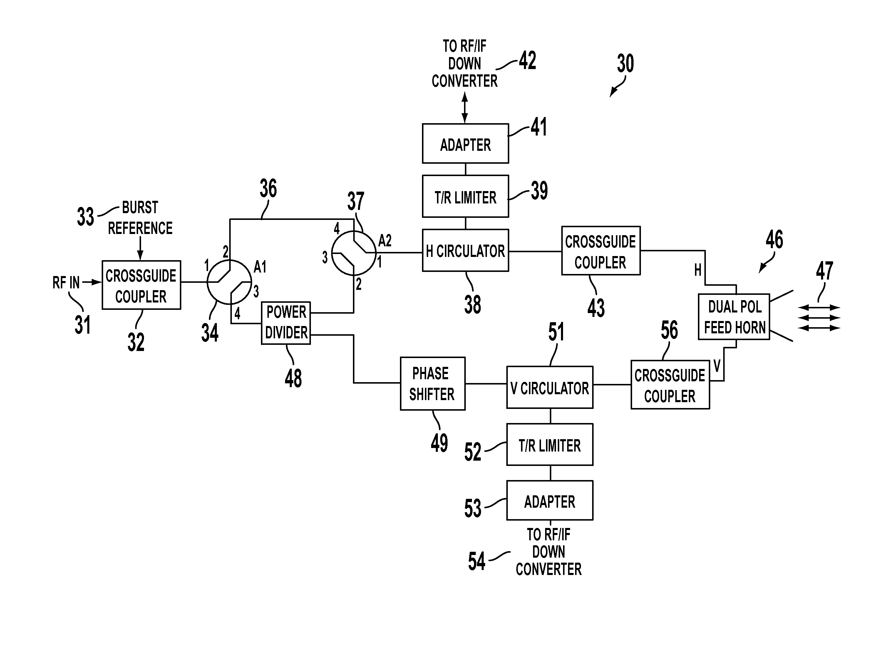
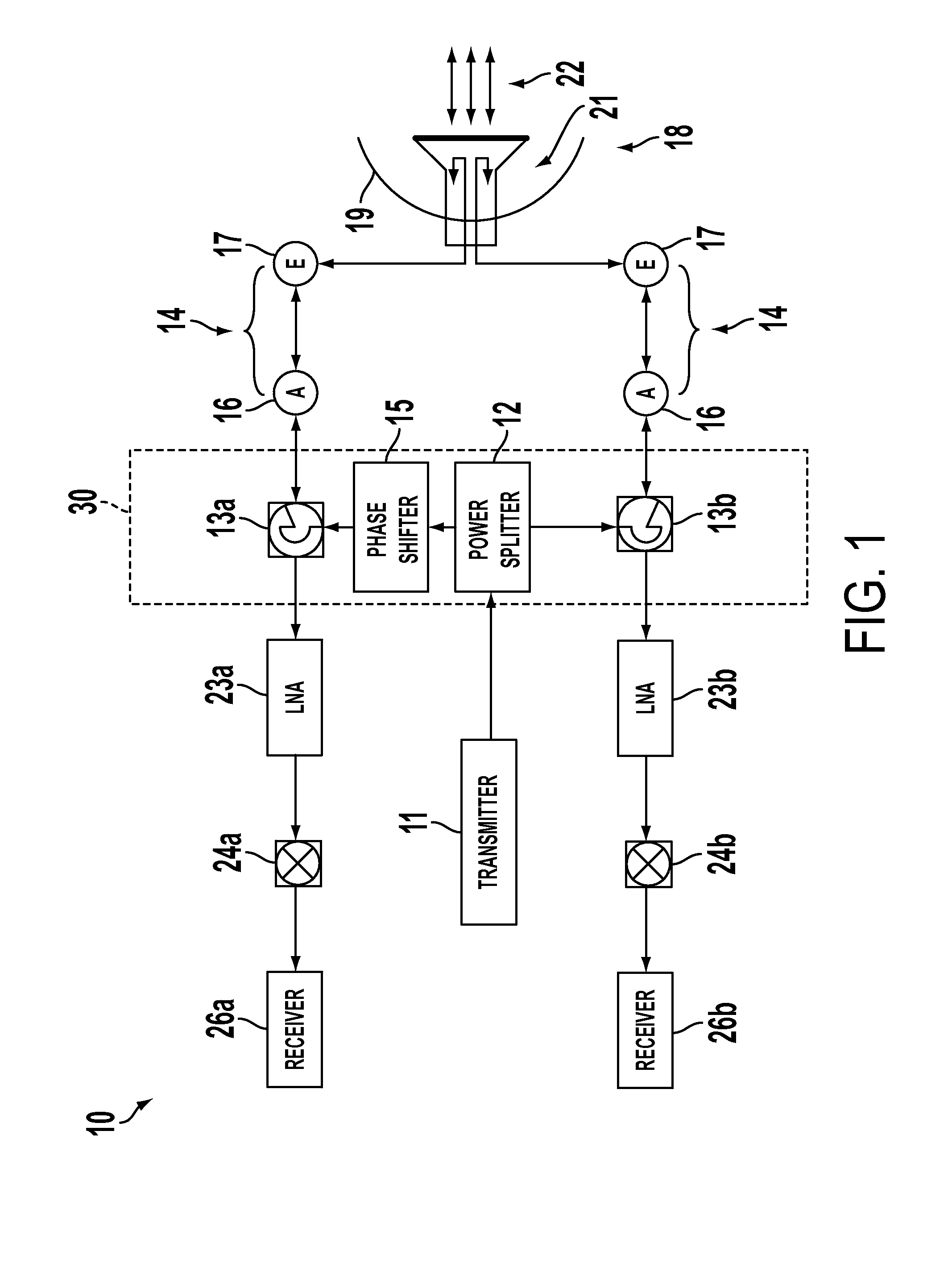
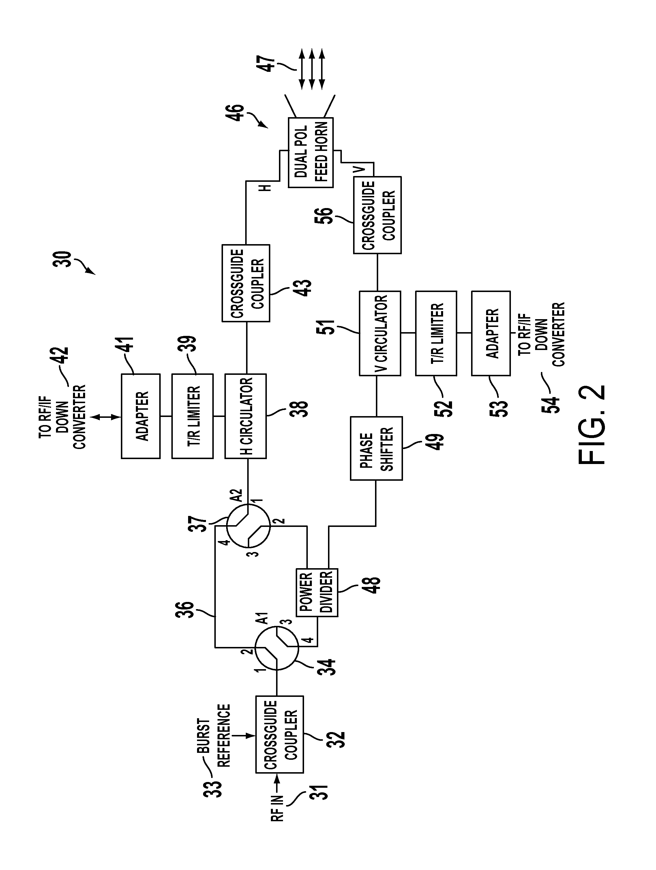
[0020]It will be noted initially that existing simultaneous dual polarization weather radar systems employ the use of a power splitter to equally divide the transmitter output into two independent transmission paths, one path for horizontal polarization and one path for vertical polarization. The two transmission paths are connected to an orthogonal mode transformer or “OMT”, that is part of the overall antenna feed subsystem. When the two signals are combined in the OMT, the actual radiated polarization pattern is the result of the vector sum of the two independent signals. The resulting polarization state is therefore dependent on the system differential phase upon transmission between the vertical and horizontal channels.

[0021]Slight differences in the length and geometry between the two waveguide channels cause each channel to have different propagation effects resulting in a random, uncontrolled, yet stable differential phase upon transmission. This ultimately results in a rand...


PUM


Abstract

An apparatus and method for the pre and post processing of radar signals to allow for improved measuring of circular depolarization ratio data in a weather radar. The system uses a phase shifter, which is periodically calibrated to ensure proper polarity, to alter the transmission phase of one channel of a radar transmission output. Reflectivity signals are then processed in accordance with rules dependent upon the transmission phase shift to reliably extract circular depolarization ratio (“CDR”) data from the reflectivity signals. CDR data is used to enhance hydrometer recognition in a weather radar system.

Description

[0001]This application claims the benefit of filing priority under 35 U.S.C. §119 and 37 C.F.R. §1.78 of the U.S. Provisional Application Ser. No. 61 / 783,286 filed Mar. 14, 2013, for a SYSTEM AND METHOD FOR MEASURING CIRCULAR DEPOLARIZATION RATIO IN A RADAR, and also claims the benefit of filing priority under 35 U.S.C. §119 and 37 C.F.R. §1.78 of the U.S. Provisional Application Ser. No. 61 / 805,510 filed Mar. 26, 2013, for a SYSTEM AND METHOD FOR MEASURING CIRCULAR DEPOLARIZATION RATIO IN A RADAR (APPL. NO. 2). All information disclosed in those prior provisional applications is incorporated herein by reference.FIELD OF THE INVENTION[0002]The present invention relates generally to weather radar systems. In particular, the present invention relates to radar transmission techniques in simultaneous dual polarization radars. In greater particularity, the present invention relates to post processing of reflectivity data received in a simultaneous dual polarization radar.BACKGROUND OF TH...

Claims


Application Information

Patent Timeline
Patent Type & Authority Patents(United States)
IPC IPC(8): G01S13/95G01S7/02H01Q21/24
CPCG01S13/95G01S7/026H01Q21/245G01S7/03G01S7/034Y02A90/10
Inventor RYZHKOV, ALEXANDER V.KNIGHT, MICHAEL BRUCEMAY, RYAN MICHAEL
Owner CLIMAVISION OPERATING LLC
Why Eureka
Try Eureka