

Laryngoscope
a technology of laryngoscope and ophthalmology, which is applied in the field of laryngoscope, can solve the problems of difficult intubation of the airway, and achieve the effect of high flexibility
- Summary
- Abstract
- Description
- Claims
- Application Information
AI Technical Summary
Benefits of technology
Problems solved by technology
Method used
Image

Examples
exemplary embodiment 1
B. Exemplary Embodiment 1
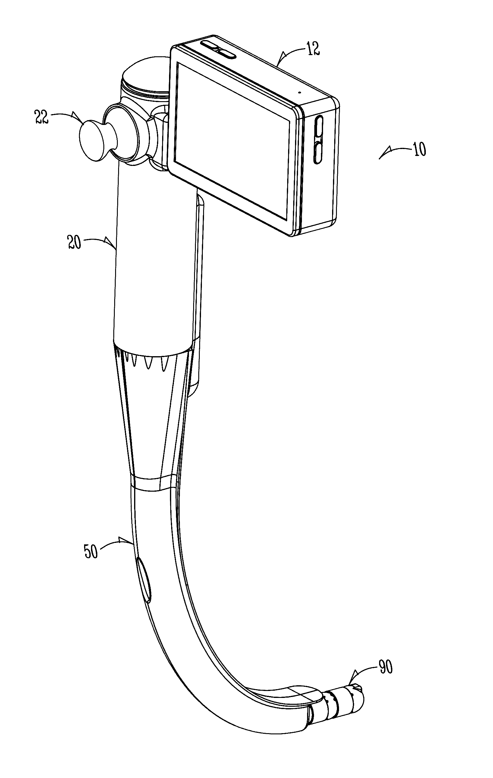
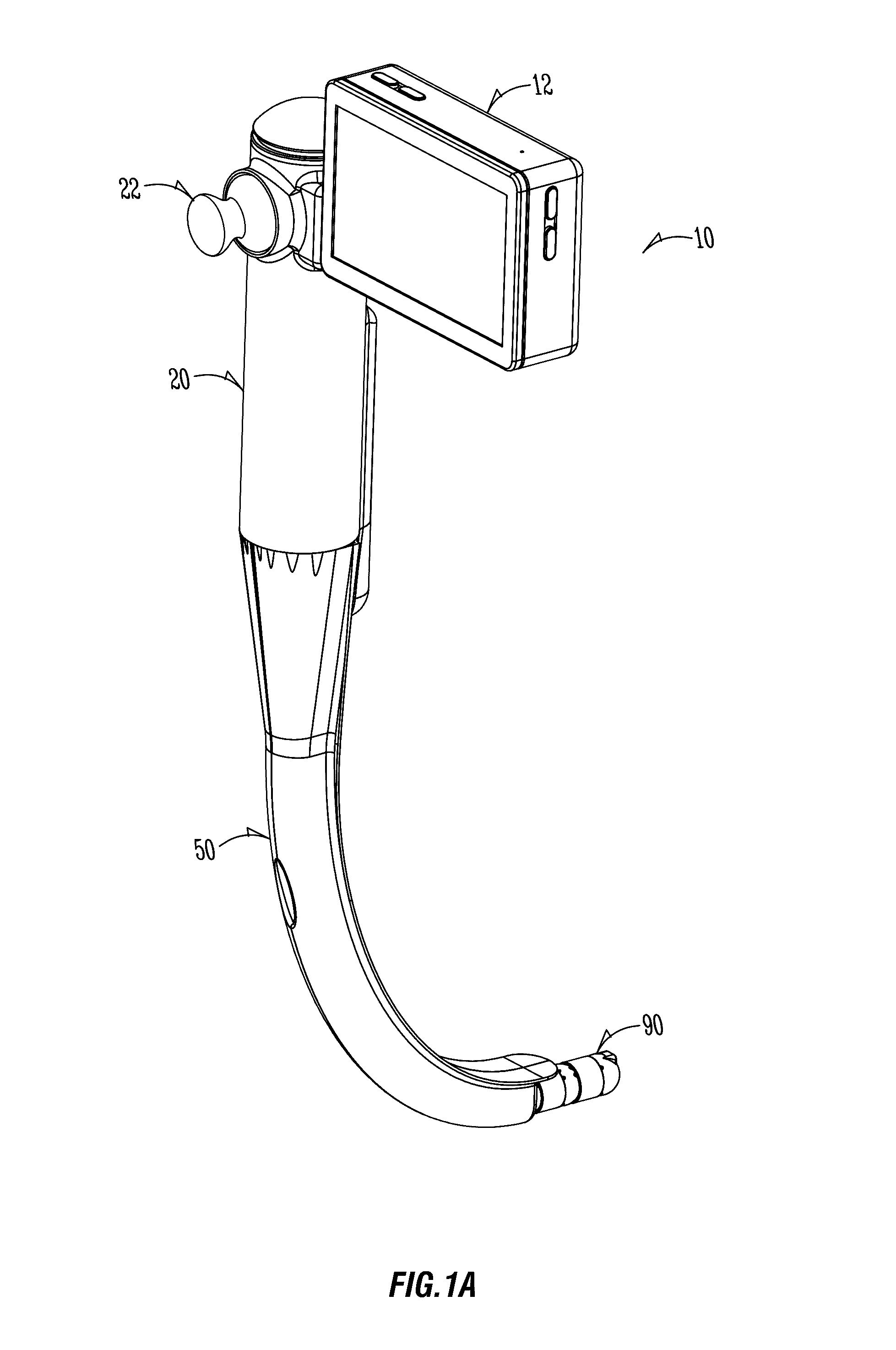
[0062]A first embodiment of a form the invention can take is shown in assembled form in FIG. 1A. It is self-contained in the sense an on-board electrically actuated system can change orientation of the working distal end by actuators inside the device along with a battery power source. The working distal end essentially functions as a manipulatable stylet guide. A manually operable joystick is integrated into the device. A display screen also allows the user camera-vision at the distal end by an onboard camera and illumination source that, through fiber optics, have a field of view that is illuminated at the distal end of the working end.
[0063]The device can be held and operated by one hand. It allows insertion of the distal end into the patient, view on a display screen of the anatomy around and ahead of the distal end, and then highly controllable manipulation (e.g. by the thumb of one hand gripping the device) of orientation of the working end of the devi...
embodiment 2
C. Embodiment 2
1. Apparatus
[0117]FIGS. 21A-C to FIG. 25 illustrate in various views a laryngoscope assembly 108 according to another exemplary embodiment of the present invention. As indicated in FIG. 21A, a scope body 110 includes a proximal open end 114 through which a camera cable 144 can be inserted to connect such cable 144 to a micro camera 140 at the distal end 112 of the scope body 110. The proximal end opening 114 also receives a stylet guide 120 that extends through the longitudinal bore of the scope body 110 to right at or near its distal end 112. A stylet 130 can thus be inserted and threaded axially through the stylet guide such that it can be moved out of the distal end of the scope body along a guided pathway determined by the orientation of the distal end of the stylet guide. This can serve as a guide over which an endotracheal tube can be advanced into the patient. The orientation and / or shape of the distal end of the stylet influences the trajectory or path of the ...
embodiment 3
D. Embodiment 3
[0138]An alternative that may be preferred is diagrammatically illustrated at FIGS. 27A-C. FIG. 27A is similar to FIG. 26A in showing a distal end 232A of a stylet 230 which can be manipulated into different orientations relative to a home or reference position.
[0139]A main difference in this embodiment is that it is the stylet 230 that is adjusted in shape, not a stylet guide. As indicated at FIG. 27A, by curling, bending, angling, or otherwise altering distal end 232A, its trajectory or the path it would take in the patient's throat when it is extended into that throat can be varied.
[0140]In this example, stylet 230 is made of a material that is somewhat flexible. As indicated, see also FIGS. 27B and C, four wires or strips are radially spaced around the longitudinal axis of stylet 230 (here 90 degrees apart). As will be appreciated, if one of those wires or strips 261, 262, 263, or 264 were pulled proximally or the material of which they were made could cause them ...
PUM
 Abstract
Description
Claims
Application Information