Method for aligning a sensor device

a sensor and receiver technology, applied in the direction of electromagnetic transmission, close-range type systems, electrical equipment, etc., can solve the problems of providing indirect and consequently incomplete information about the actual alignment of the transmitter and the receiver, the emission characteristics of the alignment laser on the one hand and the transmitter on the other hand often do not match, and the point of impact of the alignment beam on the receiver unit or the transmitter unit is poorly visibl

Active Publication Date: 2016-11-22
LEUZE ELECTRONICSLEUZE ELECTRONICS GMBH & CO KG
View PDF110 Cites 5 Cited by
  • Summary
  • Abstract
  • Description
  • Claims
  • Application Information

AI Technical Summary

Benefits of technology

[0035]This ensures that no hazardous situations occur during the alignment process as a result of the safety sensor being used for the alignment operations. This changeover into a safe mode may occur, for example, by having the alig...

Problems solved by technology

The general disadvantage of this procedure is that it is not the beam axes of the light curtain itself, which beam axes are formed by the individual light beams of the transmitter, that are aligned.
The alignment beams, as an additional light axis, thus only provide indirect and consequently incomplete information about the actual alignment of the transmitters with the receivers.
Such inaccuracies result in particular from tolerances in the mounting position of the alignment laser.
Furthermore, the emission characteristics of the alignment laser on the one hand and the transmitter on the other often do not match.
Nonetheless, and particularly o...

Method used


Image

  • Method for aligning a sensor device
  • Method for aligning a sensor device
  • Method for aligning a sensor device

Examples


Embodiment Construction

[0008]The purpose of the invention is to provide a method and a system which enable the exact and reproducible alignment of a sensor system with minimal input of time and effort.

[0009]The features of the independent claims are intended to solve this problem. Advantageous embodiments and practical further developments of the invention are described in the subclaims.

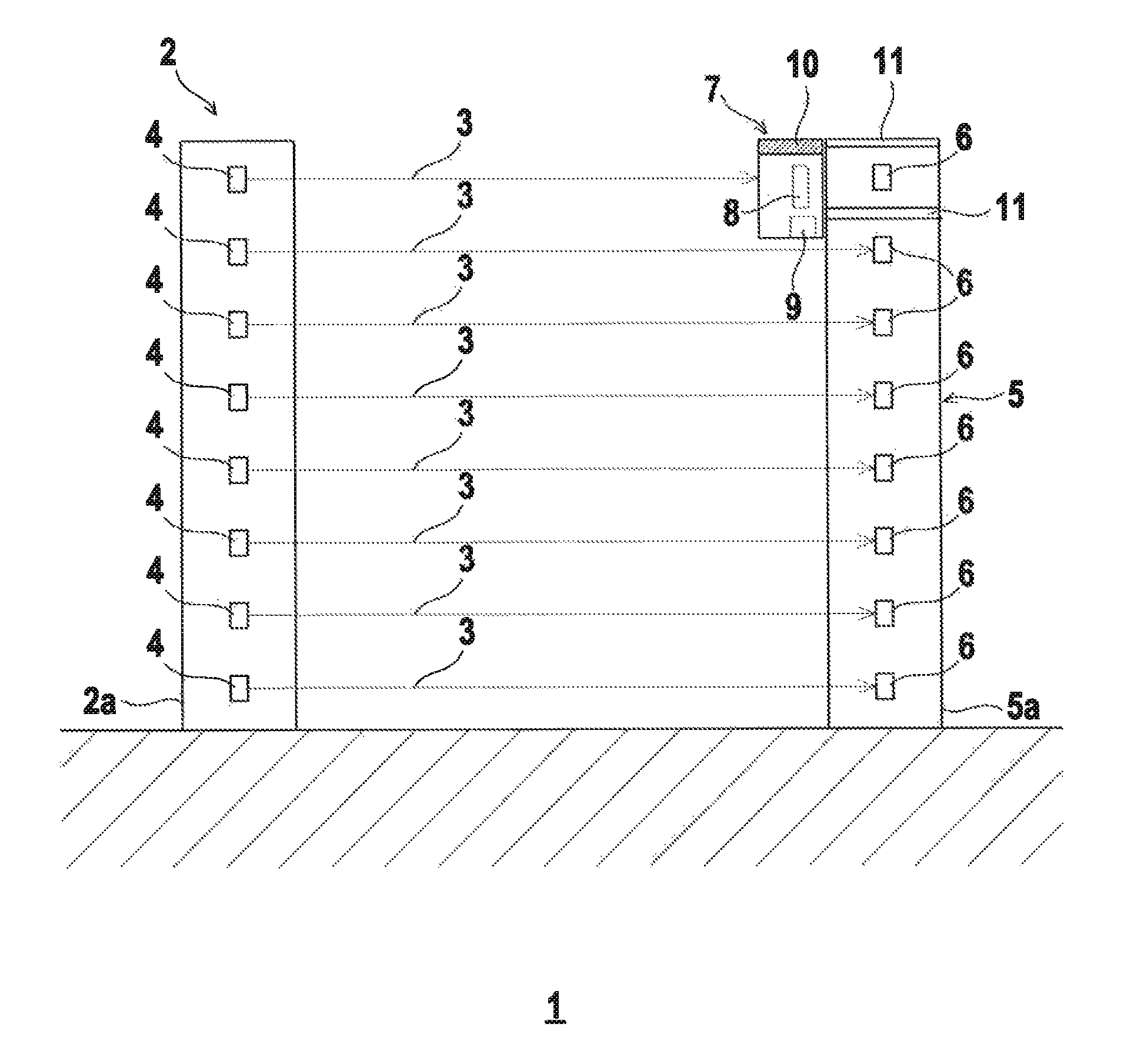
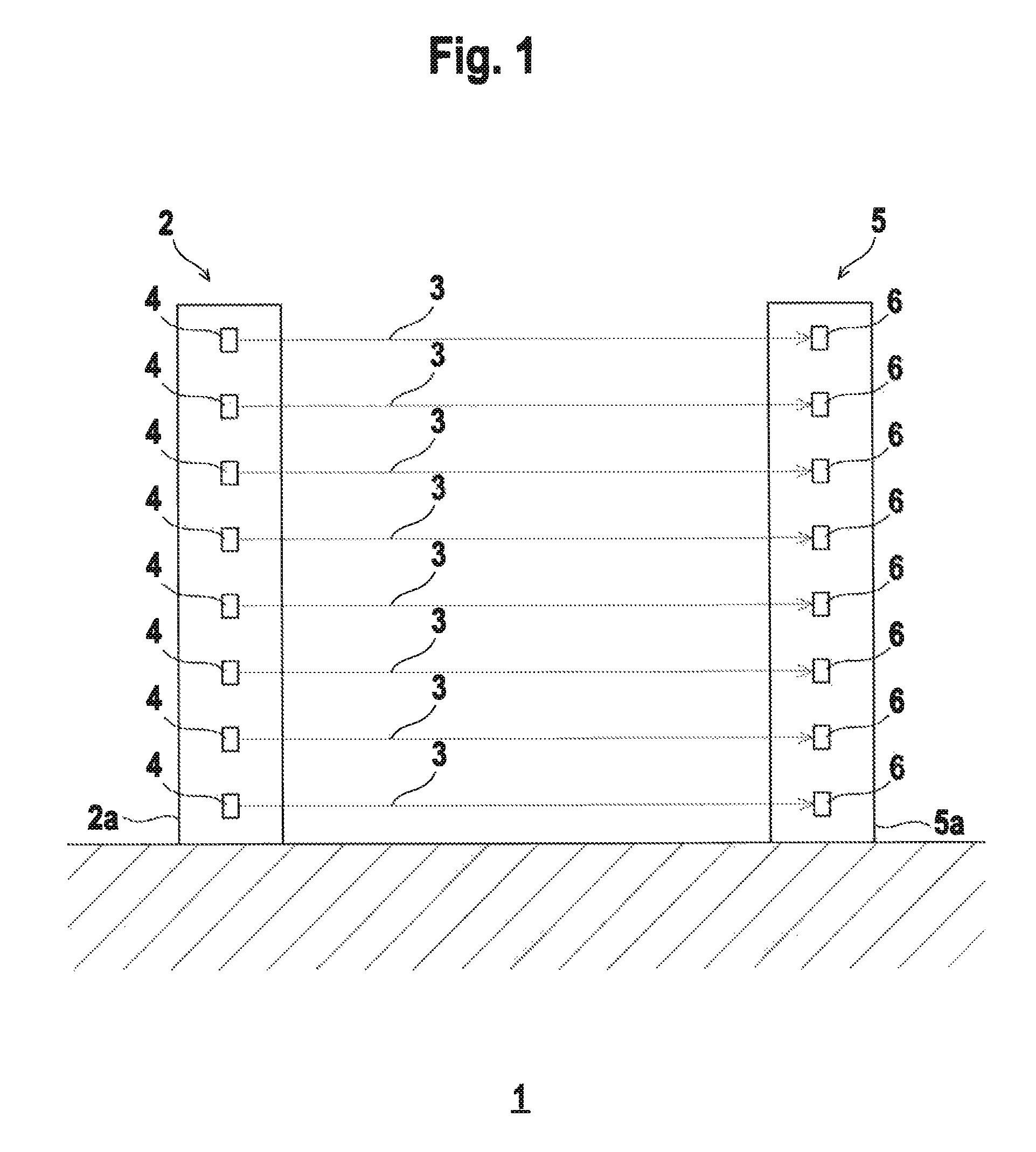
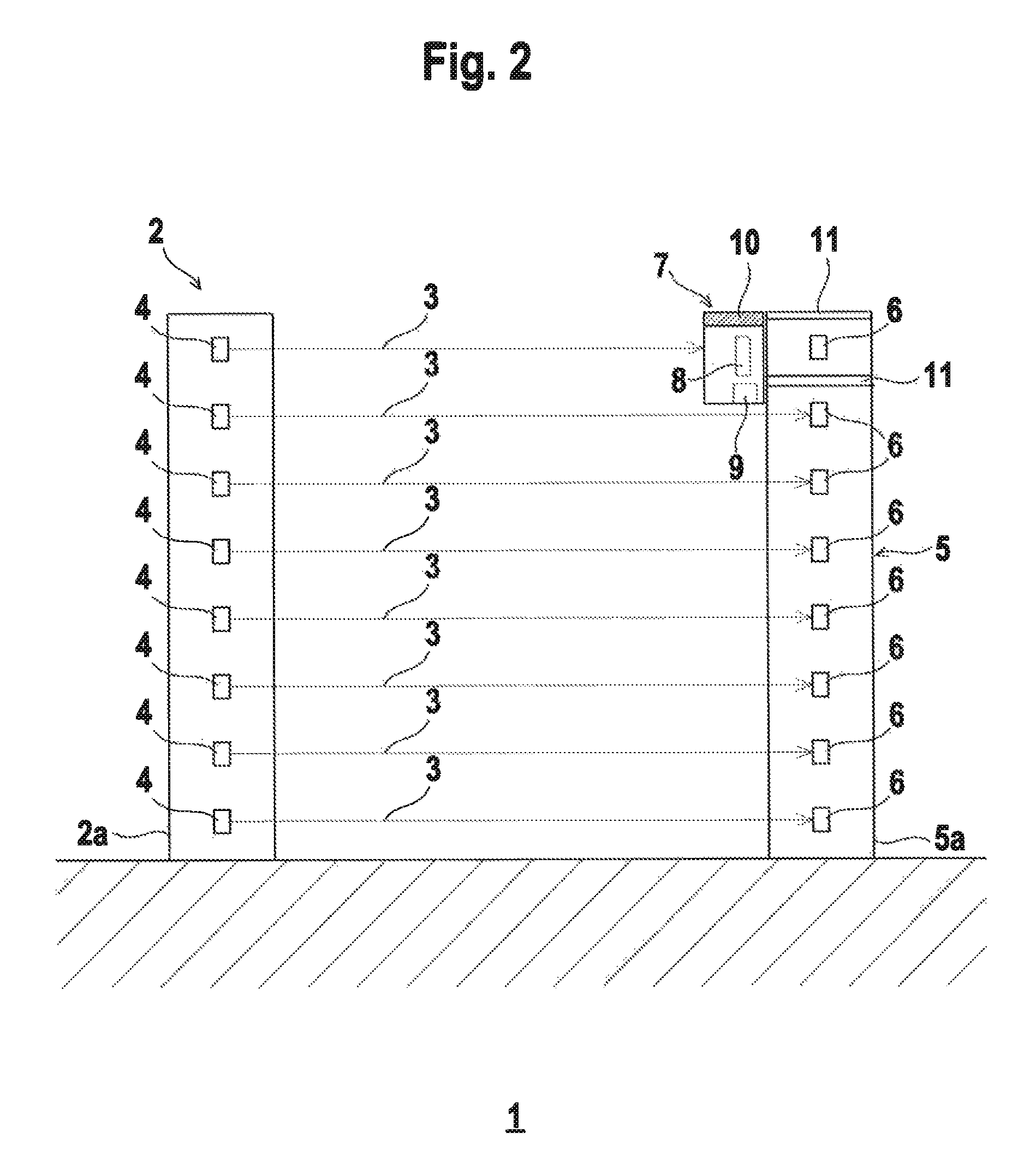
[0010]The invention relates to a method for aligning a sensor system having a transmitter unit with at least one light beam emitting transmitter and a receiver unit with at least one receiver assigned to the transmitter, which receives the light beams of the transmitter when the sensor system is in operation. To align the transmitter unit, an alignment receiver is placed on the receiver unit in front of the receiver; this alignment receiver has a larger aperture angle than the receiver itself. The light beams emitted by the transmitter are received by the alignment receiver. Data are displayed on a display unit depending o...


PUM


Abstract

The invention relates to a method for aligning a sensor system, said sensor system having a transmitter unit having at least one light beam emit-ting transmitter and a receiver unit having at least one receiver as-signed to the transmitter, which receiver receives the light beams from the transmitter when the sensor system is in operation. In order to align the transmitter unit, an alignment receiver is positioned on the receiver unit in front of the receiver, said alignment receiver having a larger aperture angle than the receiver. The light beams emitted by the transmitter are received by the alignment receiver. Depending on the quantity of light of the light beams received by the alignment receiver, data are displayed on a display unit.

Description

CROSS-REFERENCE TO RELATED APPLICATIONS[0001]This application claims the benefit under 35 USC 119 of European Application EP 14180502.8 filed on Aug. 11, 2014; all applications are incorporated by reference herein in their entirety.BACKGROUND[0002]The invention relates to a method for aligning a sensor system, and an alignment receiver for implementing the method.[0003]Such sensor systems may be realized in particular in the form of light curtains. Such a light curtain comprises a transmitter unit with an arrangement of light beam emitting transmitters and a receiver unit with an arrangement of light beam receiving receivers. For detection of objects within a monitored area, the transmitter unit and the receiver unit are arranged at opposing edges of the monitored area such that, if the monitored area is empty, the light beams emitted from each transmitter strike its corresponding receiver. An object entering the monitored area is recognized in that at least one of the beam axes for...

Claims


Application Information

Patent Timeline
IPC IPC(8): H04B10/00H04B10/114G01V8/20
CPCH04B10/1143G01V8/20
Inventor GRIMM, HANSBISCHOF, STEFAN
Owner LEUZE ELECTRONICSLEUZE ELECTRONICS GMBH & CO KG
Why Eureka
Try Eureka