Method for measuring chemical emissions

a chemical emission and measurement method technology, applied in the direction of fluid leakage detection, fluid tightness measurement, instruments, etc., can solve the problems of aging plants, industrial components, and high risk of gas leakage and chemical emission escape to the atmosphere, and fids are of limited utility, and must be res

Inactive Publication Date: 2002-06-20
GAS TECH INST
View PDF0 Cites 7 Cited by
  • Summary
  • Abstract
  • Description
  • Claims
  • Application Information

AI Technical Summary

Benefits of technology

[0011] It is yet another object of this invention to provide a test device that requires a minimal amount of input from an operator to generate useable test data.

Problems solved by technology

Industrial components, especially in aging plants, are highly susceptible to gas leaks and the escape of chemical emissions to the atmosphere.
FIDs are of limited utility for components that are leaking heavily in that if the gas emissions exceed 90,000 ppm the FID "flames out" and must be reset.
Neither of the above-described methods is capable of measuring the quantity of the gas emitted but only the concentration of the emitted gas in a plume.
Because the concentration of the emitted gas varies significantly with speed and direction of wind, the angle of the probe, the distance of the probe from the leak, the geometry of the leaking component and the flow rate of the sample through the instrument, attempts to correlate the leak rate with the concentration have been unsuccessful.
This process was time consuming and therefore very expensive.
The test device thereby signals whether the test result is sufficient or whether the test result is unreliable based upon the presence of interference from another leaking component, presence of the chemical in the background air or incomplete capture of the leak.

Method used


Image

  • Method for measuring chemical emissions
  • Method for measuring chemical emissions

Examples


Embodiment Construction

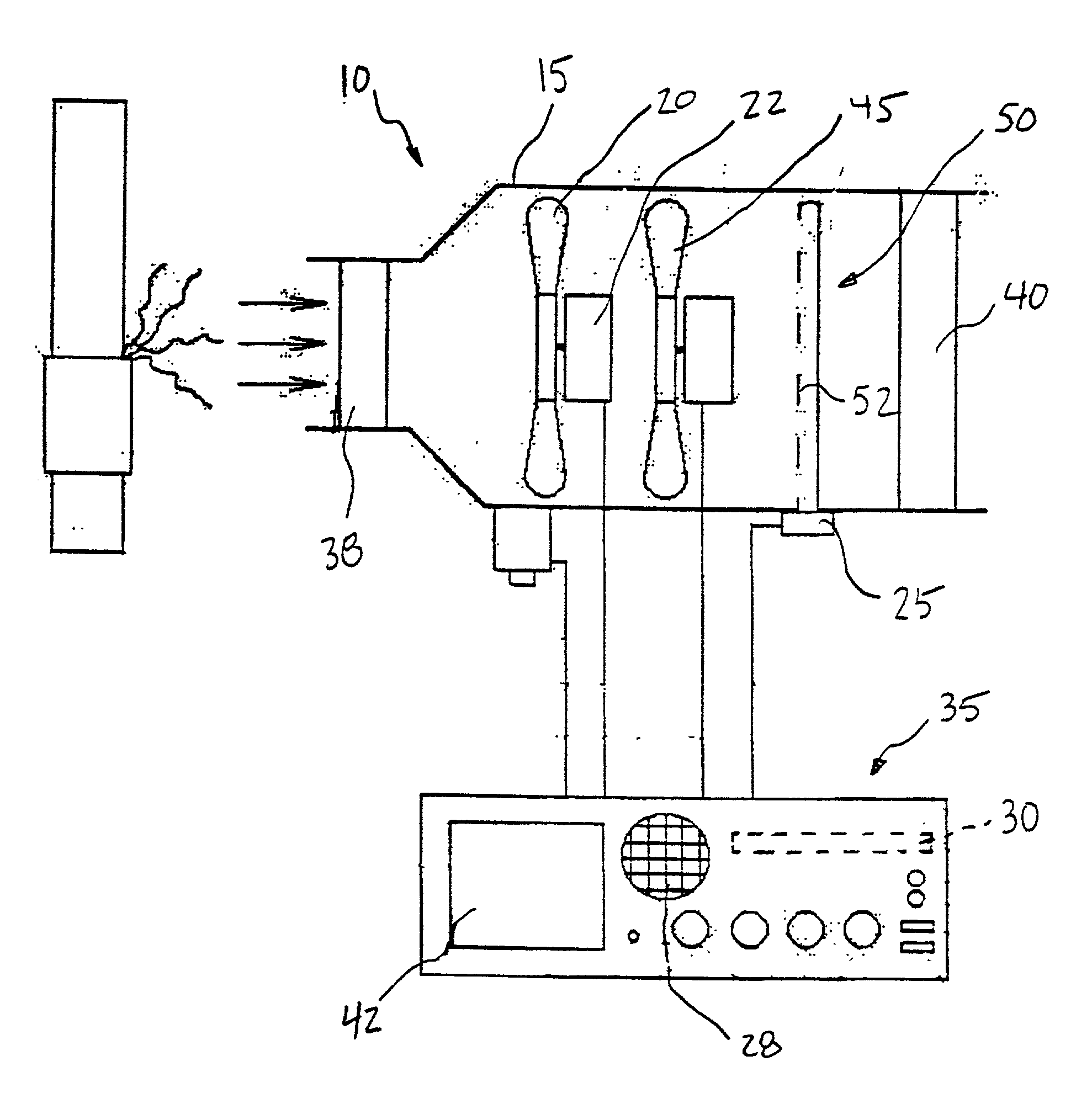
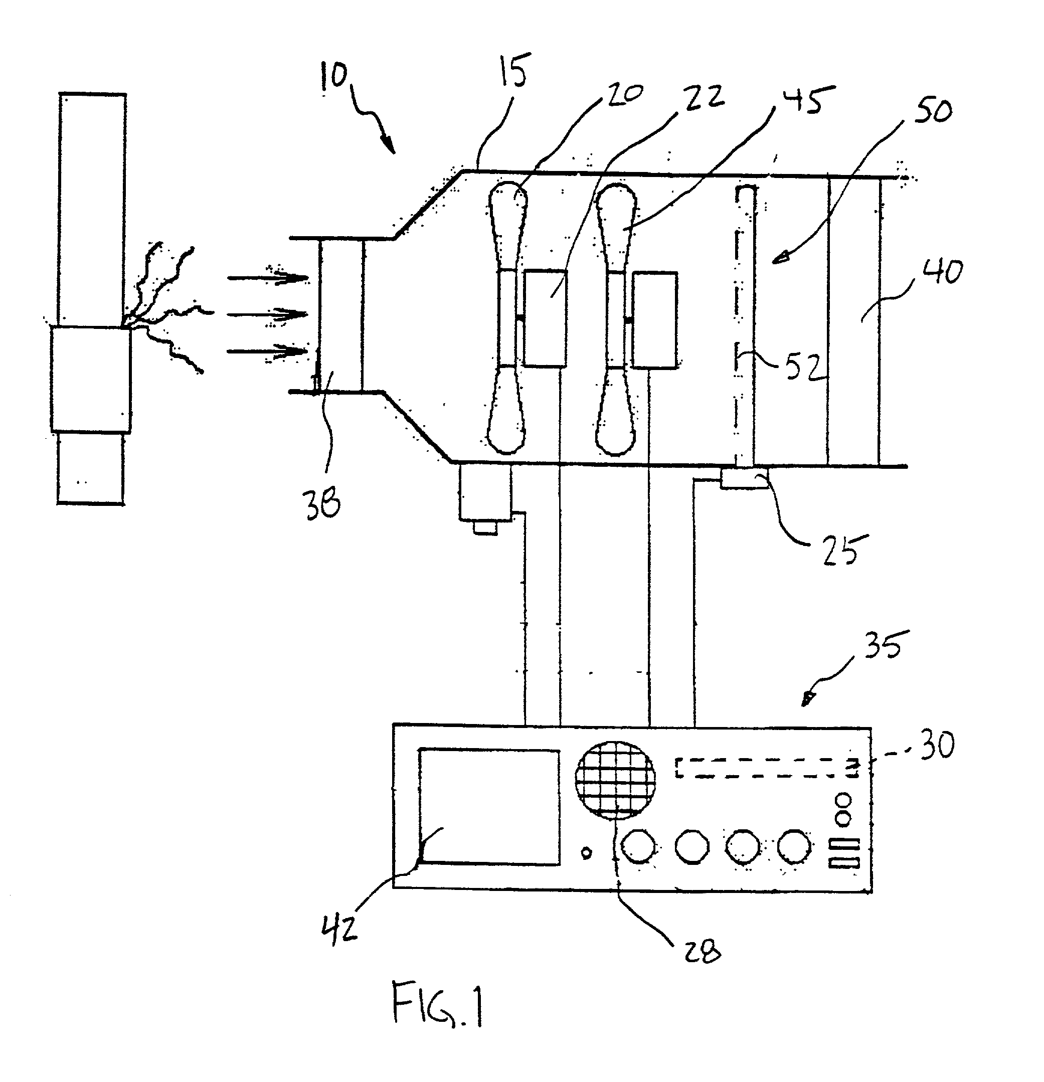
[0022] FIG. 1 shows test device 10 for measuring chemical emissions to the atmosphere. Test device 10 includes housing 15 for containment of one or more important components of test device 10. Housing 15 is preferably manufactured from polyurethane or other conductive, static resistant, material known to those having ordinary skill in the art. Additionally, housing 15 is preferably portable and easily carried by an operator.

[0023] Air mover 20, such as fan or impeller, is positioned within housing 15 or attached to housing 15 with a hose (not shown). Air mover 20 is likewise preferably constructed from a static resistant material. Air mover 20 is arranged within housing 15 to draw ambient air directly into housing 15. Air mover 20 is preferably connected with respect to motor 22 and is preferably capable of operating in at least two speeds, a high flow rate and a low flow rate.

[0024] Motor 22 preferably comprises a brushless motor mechanically connected to air mover 20. A brushless ...


PUM

PropertyMeasurementUnit
alarm thresholdaaaaaaaaaa
flow rateaaaaaaaaaa
flow rateaaaaaaaaaa

Abstract

A test device for measuring chemical emissions to the atmosphere from a leaking component that includes a housing containing an air mover for drawing ambient air directly into the housing. The air mover is capable of operating at a high flow rate and a low flow rate. A detector for detecting the presence of a chemical emission is positioned within the housing as well as a calculator for measuring the concentration of the chemical emission. Air is drawn directly into a housing at a low flow rate in a survey mode and once a leak is detected air is drawn directly into the housing at a high flow rate in a quantification mode. During the quantification mode the calculator determines a leak rate from the leaking component or alternatively indicates that the calculated leak rate is unreliable.

Description

[0001] 1. Field of the Invention[0002] This invention relates to a test device for the detection and measurement of chemical emissions to the atmosphere.[0003] 2. Description of Related Art[0004] Industrial components, especially in aging plants, are highly susceptible to gas leaks and the escape of chemical emissions to the atmosphere. As a result, leak detection and measurement is an important safety and cost-saving tool within industrial plants.[0005] A common method that is still employed for detecting leaks is covering a suspect component in soapy water to identify the leak. Alternatively, "sniffer" devices that use a flame ionization detector (FID) or other sensor to detect leaking gas can be used to find and identify the presence of a leak. FIDs are of limited utility for components that are leaking heavily in that if the gas emissions exceed 90,000 ppm the FID "flames out" and must be reset. Neither of the above-described methods is capable of measuring the quantity of the g...

Claims


Application Information

Patent Timeline
Patent Type & Authority Applications(United States)
IPC IPC(8): G01M3/20G01M3/22G01N1/22G01N1/24
CPCG01M3/20G01M3/223G01N1/2202G01N2001/2241G01N1/24G01N2001/2223G01N1/2226
Inventor WEBB, MICHAELLOTT, ROBERT
Owner GAS TECH INST
Why Eureka
Try Eureka