Device for increasing the heating and cooling output of a heat pump in heat reclamation in air conditioning units

a heat pump and heat reclamation technology, which is applied in the field of heat reclamation, can solve the problems of increasing the temperature of the heat transfer medium, reducing efficiency, and unsatisfactory heat transfer effect of the heat pump, and achieve the effect of reducing the input of primary energy

Inactive Publication Date: 2011-02-24
HOMBUCHER HEINZ DIETER
View PDF3 Cites 8 Cited by
  • Summary
  • Abstract
  • Description
  • Claims
  • Application Information

AI Technical Summary

Benefits of technology

[0026]Due to the inventive cooperation of the device components, it is possible to keep the supply air temperature constant or to readjust the supply air temperature in accordance with specifications for a maximum energy yield and a minimal input of primary energy. In the terms of VDI 2071, a heat reclamation of up to 100% is achieved, wherein the temperature level of the exhaust air may be higher or lower than the temperature level of the supply air.

Problems solved by technology

In conventional heat reclamation systems, when the heat pump switches on, the heat transfer medium is unevenly heated and cooled because the compressor is switched on and off, leading to uneven supply air temperatures in any air-conditioning system connected thereto.
However, all these measures lead to a decrease in the efficiency and to temperature jumps in the heat transfer medium if the output of a compressor falls below the minimum cooling output, because the compressor needs to be switched off.
In the cooling mode, it is also not always possible to transfer the energy introduced into the heat transfer medium by the compressors to the exhaust air without exceeding the permissible condensation temperature.
If the exhaust air heat exchanger ices up and a defrosting process needs to be carried out, e.g., by reversing the cooling circuit or with the aid of a bypass circuit, the cold heat exchanger cannot be replaced and the supply air heat exchanger cannot be supplied with sufficiently warm heat transfer medium in an uninterrupted fashion.
This results in different regions of the heat exchanger being acted upon unevenly and an inferior heat transfer to be adjusted as a consequence thereof.
Consequently, the solutions according to the described prior art do not make it possible to achieve a constant temperature of the heat transfer medium at the supply air heat exchanger in order to be able to set a constant supply air temperature in interconnected circulating systems.
An optimal heat exchange between the heat transfer medium and air over the entire heat exchanger surface is not possible due to the different mass flows and temperatures of the heat transfer medium.

Method used


Image

  • Device for increasing the heating and cooling output of a heat pump in heat reclamation in air conditioning units
  • Device for increasing the heating and cooling output of a heat pump in heat reclamation in air conditioning units
  • Device for increasing the heating and cooling output of a heat pump in heat reclamation in air conditioning units

Examples


Embodiment Construction

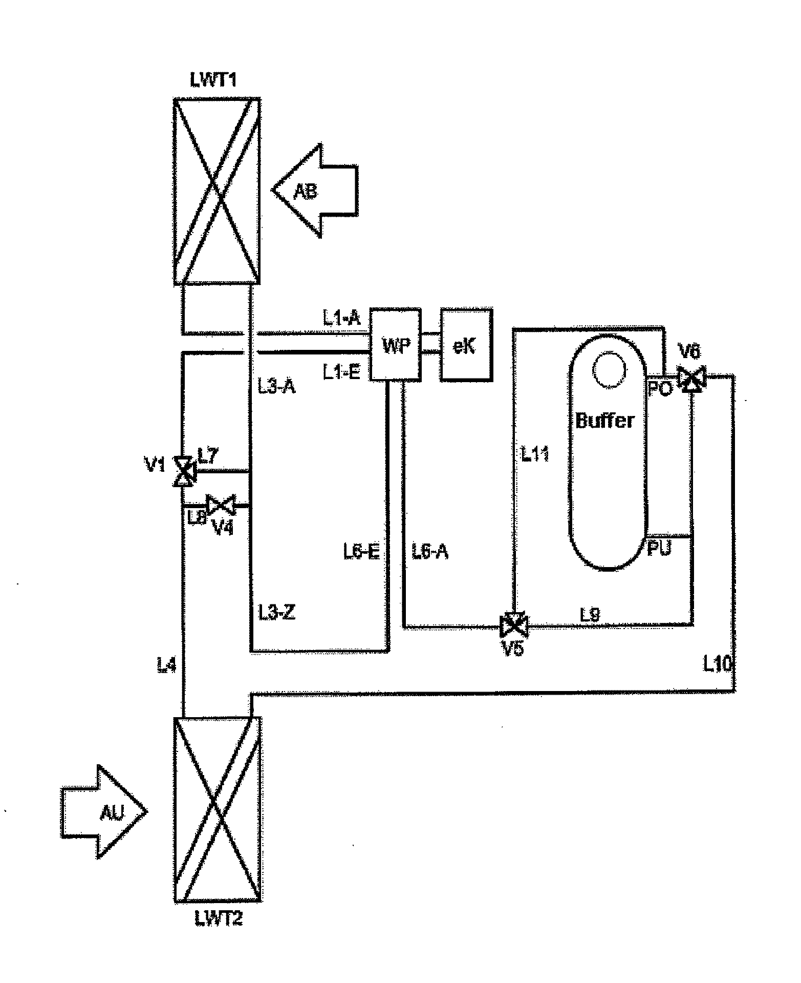
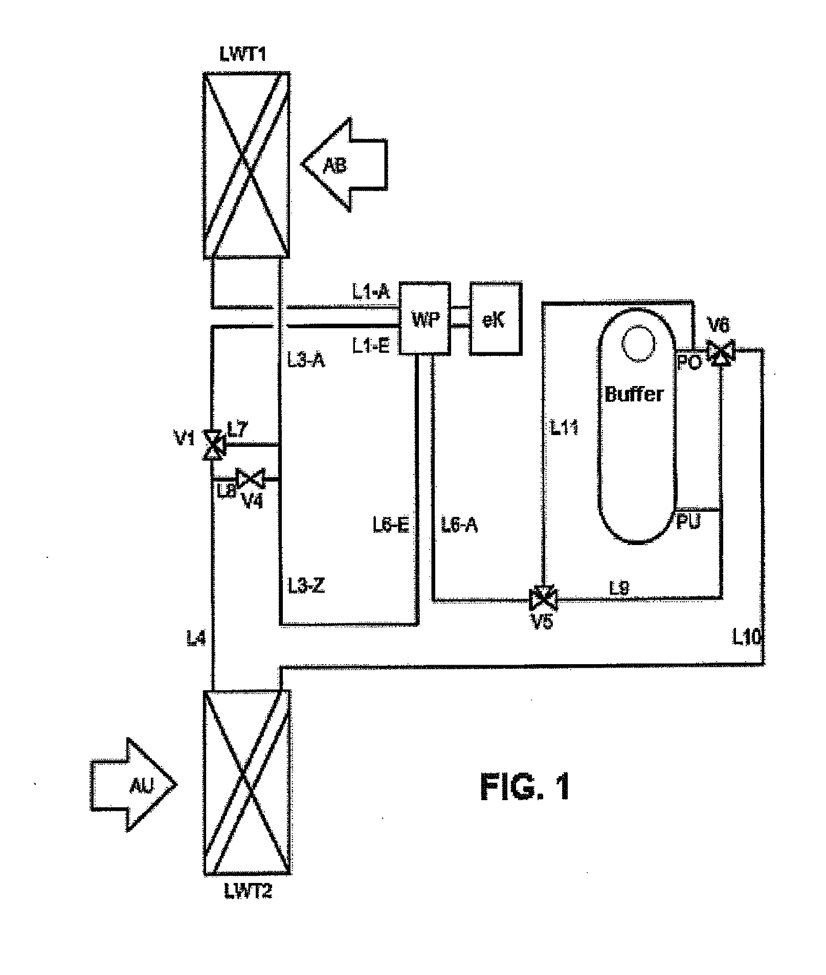
[0048]In a preferred embodiment, a circuit according to FIG. 1 is used. The hydraulic circuit is connected in such a way that it forms an interconnected circulating system when the compressor of the heat pump WP is switched off. FIG. 1 shows the basic incorporation of a buffer reservoir into an interconnected circulating system. In this case, the buffer reservoir may be realized in the form of a so-called stratified reservoir, wherein thermal energy can be stored in and withdrawn from this reservoir layer-by-layer. This is realized due to the corresponding connection with the supply lines PU, PO and the three-way valve V6. The heat pump WP furthermore is assigned to the buffer reservoir in order to supply thermal energy to this buffer reservoir.

[0049]Regarding Operating Mode 1:

[0050]Referring to the system of the FIG. 1, Operating mode 1 occurs when the compressor is switched off and without using the heat pump WP.

[0051]The heat transfer medium is conveyed in the hydraulic circuit b...


PUM


Abstract

In order to improve heat reclamation, a circulatory composite system having one heat exchanger each in a supply air volume flow and an exhaust air volume flow is provided in an air treatment system and connected to a buffer reservoir supplied by a heat pump with heat energy. In addition, a method for operating a heat reclamation system with the structure of a circulatory composite system with an integrated heat pump is designed such that the volume flow of the heat exchanger is divided in the line leading to the heat exchanger. The at least two volume flows serve to flow through the heat exchanger (compressor) of the heat pump with a larger or smaller volume flow than the heat exchanger in the supply air.

Description

CROSS-REFERENCE TO RELATED APPLICATIONS[0001]This patent application is the national phase of PCT / DE2008 / 002032, filed Dec. 4. 2008. which claims the benefit of German Patent Application Nos. 102007059332.7, filed Dec. 7, 2007; 102007061617.3, filed Dec. 18, 2007; 102008009860.4, filed Feb. 19, 2008; and 102008032201.6, filed Jul. 9, 2008.FIELD OF THE INVENTION[0002]The present invention relates generally to heat reclamation and more particularly to a device for multistage heat reclamation with controlled heating and cooling output of an air-conditioning system and to a three-stage heat reclamation system.BACKGROUND OF THE INVENTION[0003]Heat pumps and interconnected circulating systems are used for heat reclamation in ventilation engineering. In this case, cold external air in the form of supply air can be preheated and also dried, if applicable, by means of a targeted heat transfer from the warm exhaust air. Furthermore, warm external air in the form of supply air can be cooled by...

Claims


Application Information

Patent Timeline
Patent Type & Authority Applications(United States)
IPC IPC(8): F25B27/00F25B29/00
CPCF24F5/0046F24F6/00F24F11/008Y02B30/563F24F2005/0025Y02B30/52F24F12/003F24F11/83Y02B30/56Y02P80/15F24F11/84
Inventor HOMBUCHER, HEINZ-DIETER
Owner HOMBUCHER HEINZ DIETER
Why Eureka
Try Eureka