Method for in-situ magnetization or degaussing of generator rotor

a generator rotor and magnetization technology, applied in the field of in-situ magnetization and degaussing of generator rotors, can solve the problems of inability to easily regulate the operation of permanent magnet machines in constant power mode, poor efficiency, etc., and achieve the effect of lowering the current over time and lowering the curren

Active Publication Date: 2016-11-29
GENERAL ELECTRIC CO
View PDF5 Cites 10 Cited by
  • Summary
  • Abstract
  • Description
  • Claims
  • Application Information

AI Technical Summary

Problems solved by technology

Permanent magnet machines are not easily regulated.
Operation of permanent magnet machines in constant power mode can be a problem because low power factor operation is forced through flux weakening methods to reduce voltage at light loads or to minimize inverter ratings.
As a result, the machine terminal voltage becomes load dependent, efficiency suffers, and, at partial loads, the magnetic field source is underutilized.
Machines wound with excitation windings (“wound field machines”) can be regulated over a wide range of loads, but wound field machines experience winding losses that decrease machine efficiency.
Additionally, windings and excitation sources for wound field machines are sized to support the maximum requirements and thus are often expensive and under-utilized.

Method used


Image

  • Method for in-situ magnetization or degaussing of generator rotor
  • Method for in-situ magnetization or degaussing of generator rotor
  • Method for in-situ magnetization or degaussing of generator rotor

Examples


Embodiment Construction

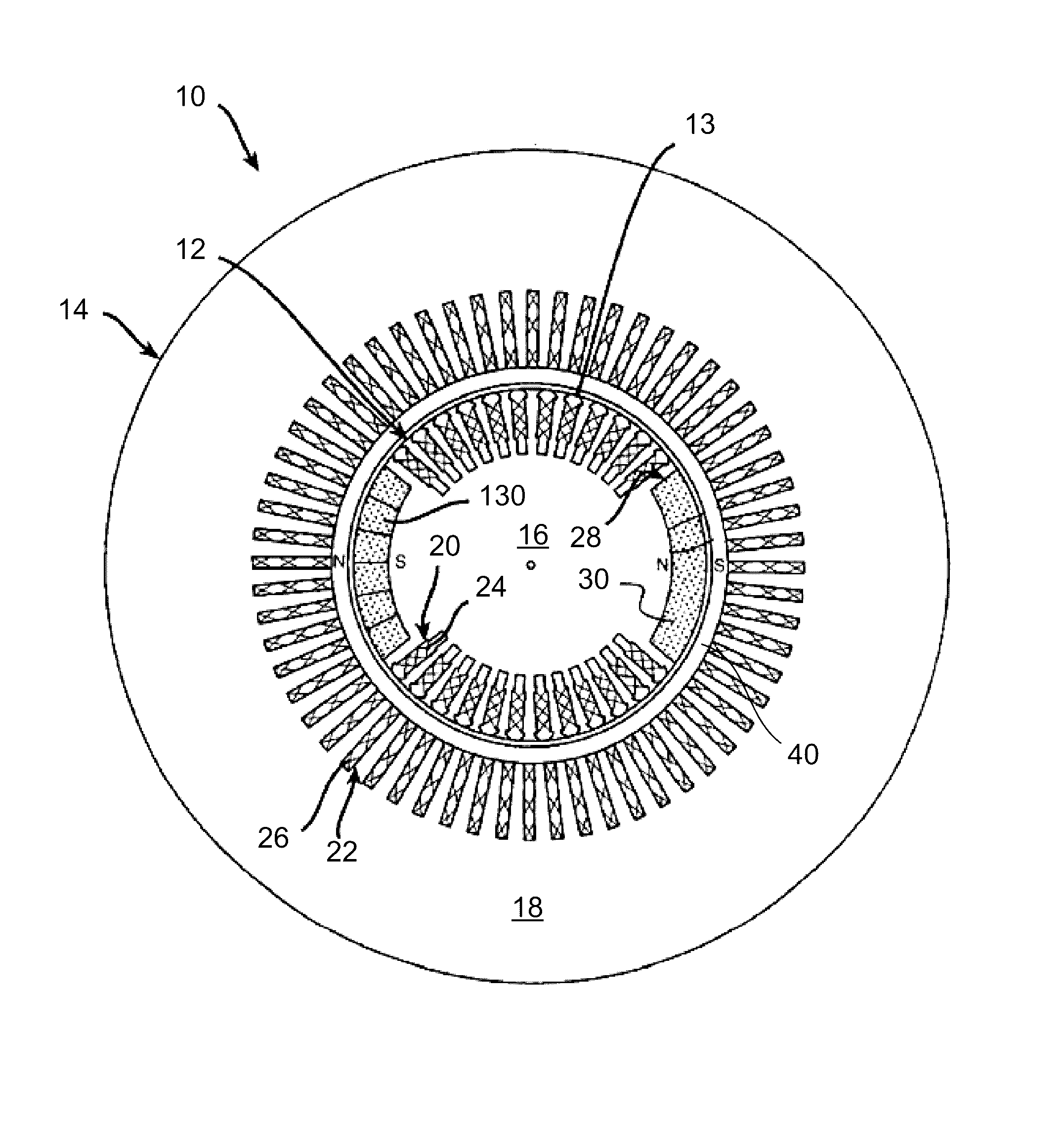
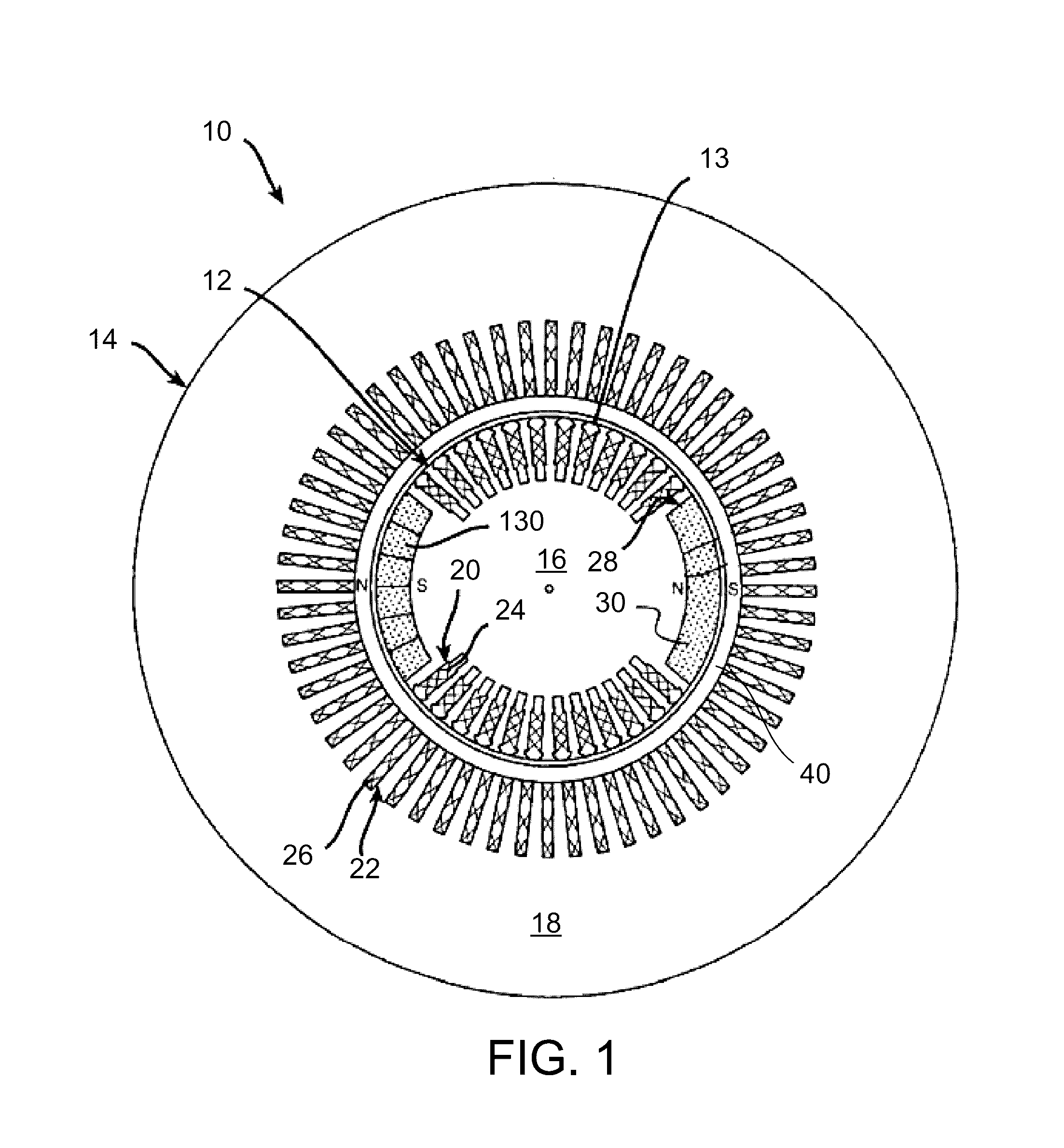
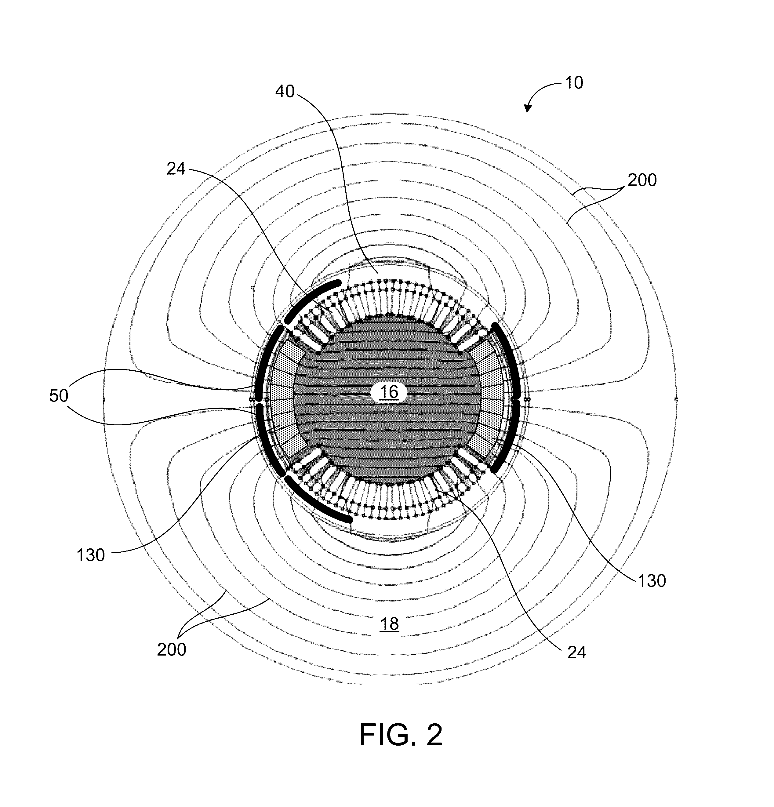
[0014]One or more specific aspects / embodiments of the present invention will be described below. In an effort to provide a concise description of these aspects / embodiments, all features of an actual implementation may not be described in the specification. It should be appreciated that in the development of any such actual implementation, as in any engineering project, numerous implementation-specific decisions must be made to achieve the developers' specific goals, such as compliance with machine-related, system-related and business-related constraints, which may vary from one implementation to another. Moreover, it should be appreciated that such a development effort might be complex and time consuming, but would nevertheless be a routine undertaking of fabrication and manufacture for those of ordinary skill having the benefit of this disclosure.

[0015]When introducing elements of various embodiments of the present invention, the articles “a”, “an” and “the” are intended to mean th...


PUM

PropertyMeasurementUnit
timeaaaaaaaaaa
duration time periodaaaaaaaaaa
magnetizationaaaaaaaaaa

Abstract

A method for in-situ magnetization of a generator rotor is provided. The generator has a stator and the rotor is located inside the stator. An air gap is formed between an outer radial portion of the rotor and an inner radial portion of the stator. The rotor has a plurality of excitation windings and a plurality of permanent magnets. The method includes the step of applying a current to the excitation windings, and the current is greater than a normal excitation current. A maintaining step maintains the current for a time period sufficient to magnetize the permanent magnets. The magnetization of the permanent magnets occurs on the rotor in-situ and while the rotor is inside the stator.

Description

BACKGROUND OF THE INVENTION[0001]The method described herein relates generally to in-situ magnetization and degaussing of generator rotors. More specifically, the apparatus relates to in-situ magnetization and degaussing of rotors incorporating permanent magnets.[0002]Most synchronous machines include either permanent magnets or excitation windings (fed by a regulated source) to provide MMF (magnetomotive force) that provides the magnetic flux for machine operation. The permanent magnets or excitation windings can be situated on either the rotor or the stator. For rotor-based embodiments, excitation power is brought through either a set of collectors (slip rings) or a brushless system that uses a small (“inside-out”) synchronous machine with a stator excitation source.[0003]Permanent magnet machines are not easily regulated. Operation of permanent magnet machines in constant power mode can be a problem because low power factor operation is forced through flux weakening methods to re...

Claims


Application Information

Patent Timeline
Patent Type & Authority Patents(United States)
IPC IPC(8): H01F13/00
CPCH01F13/003H01F13/006H02K15/03
Inventor BUSKIRK, ERIC STEVEN
Owner GENERAL ELECTRIC CO
Why Eureka
Try Eureka