
Coaxial RF switch optoelectronic indicators and method of making same

Active Publication Date: 2016-11-29
MAGVENTION (SUZHOU) LTD
View PDF1 Cites 2 Cited by
  • Summary
  • Abstract
  • Description
  • Claims
  • Application Information

AI Technical Summary

Benefits of technology

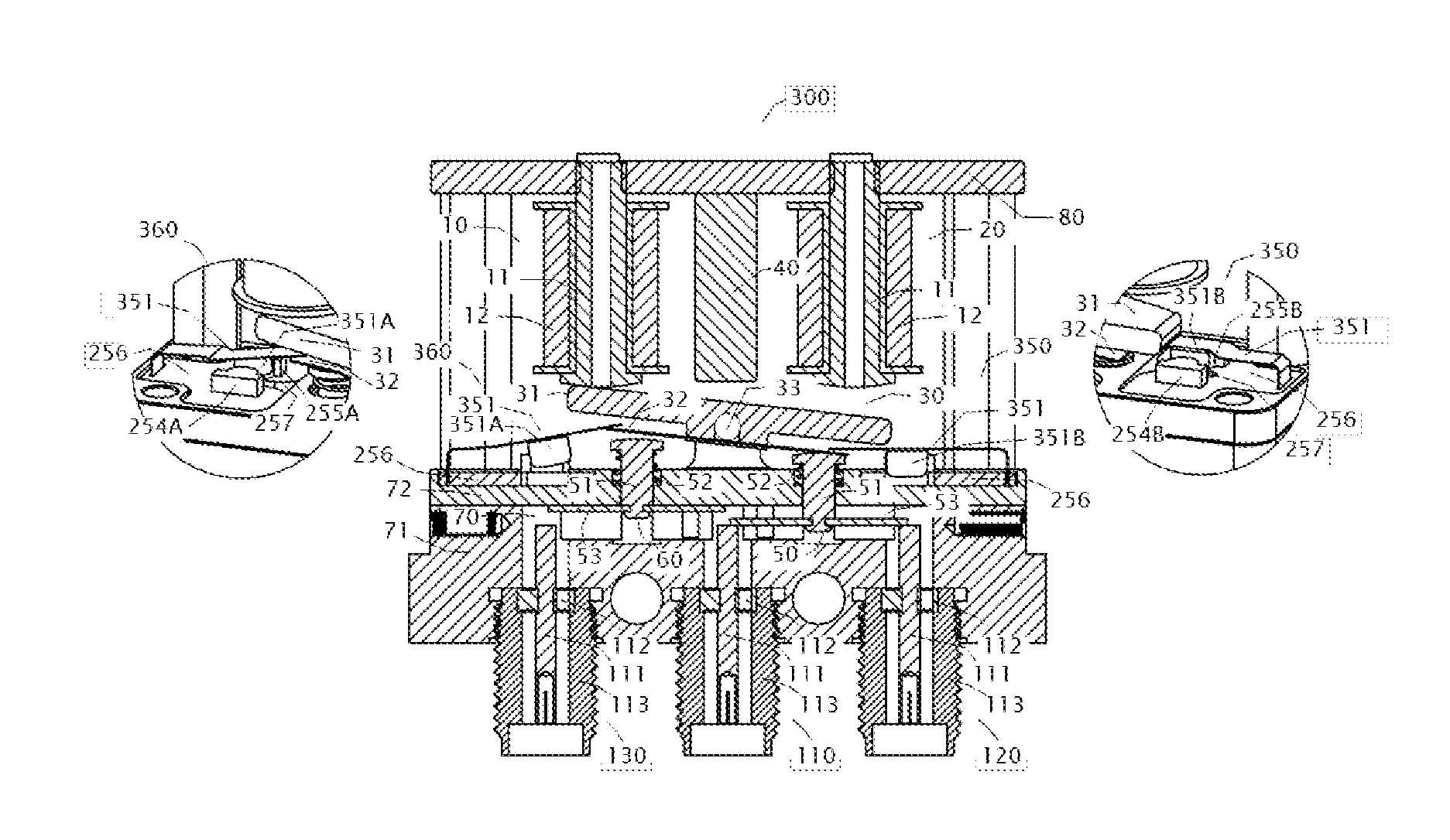
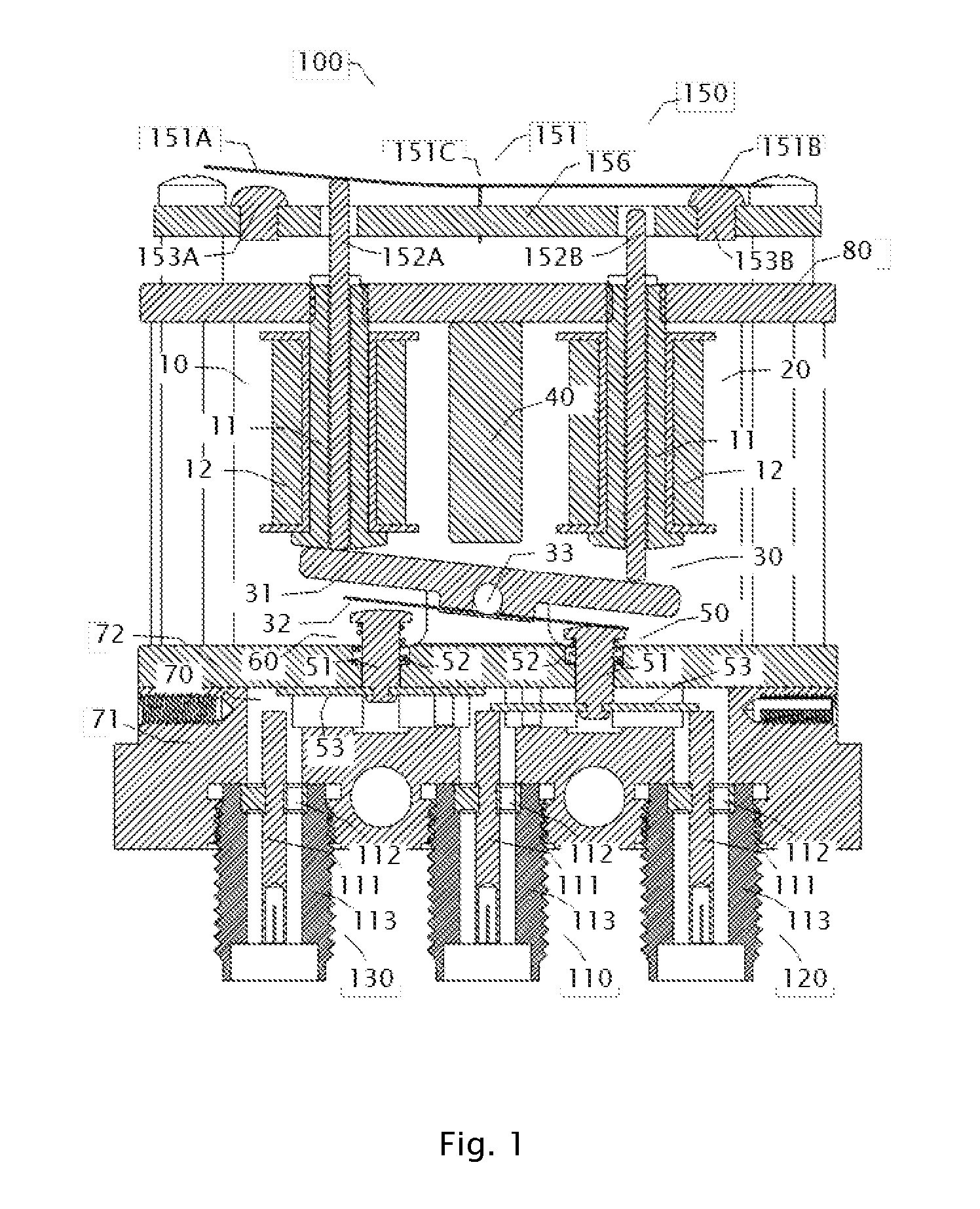
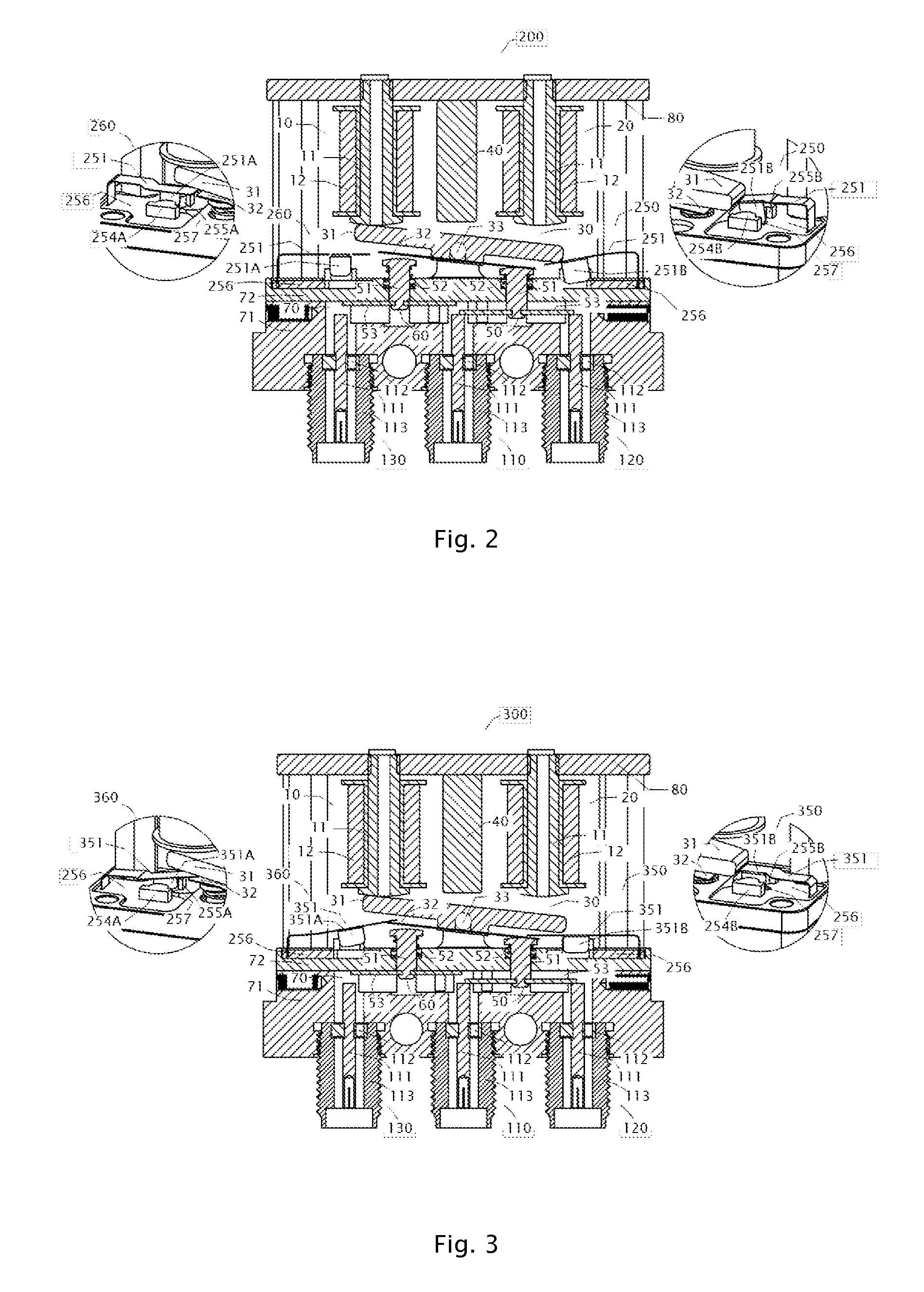
The patent is for a device that helps to indicate the status of a switch by using a light-emitting diode (LED) and a photo sensor. A shutter assembly interacts with a soft-iron rocker in the switch to open or close the optical path between the LED and photo-sensor, which corresponds to the state of an RF channel in the switch. The device provides a simple and effective way to show the status of a switch.

Problems solved by technology

However, the reliable auxiliary contact requires suitable contact pressure, which increases the complexity in tuning and adjusting the actuation mechanism of the switch.
Additionally, the auxiliary contact structure needs to interact with the switch actuation mechanisms, and thus it is difficult to form a sealed enclosure to protect the auxiliary contacts, resulting in contact failures because of contamination.
This renders the auxiliary contact indicator unreliable.

Method used


Image

  • Coaxial RF switch optoelectronic indicators and method of making same
  • Coaxial RF switch optoelectronic indicators and method of making same
  • Coaxial RF switch optoelectronic indicators and method of making same

Examples


Embodiment Construction

[0012]It should be appreciated that the particular implementations shown and described herein are examples of the invention and are not intended to otherwise limit the scope of the present invention in any way. Indeed, for the sake of brevity, conventional electronics, manufacturing, and other functional aspects of the systems (and components of the individual operating components of the systems) may not be described in detail herein. Furthermore, for purposes of brevity, the invention is frequently described herein as pertaining to an electromagnetic relay or switches for use in electrical or electronic systems. It should be appreciated that many other manufacturing techniques could be used to create the relays described herein, and that the techniques described herein could be used in mechanical relays, optical switches, fluidic control systems, or any other switching devices. Further, the techniques would be suitable for application in electrical systems, optical systems, consume...


PUM


Abstract

A coaxial RF switch optoelectronic indicator comprising a light-emitting diode (LED), a photo sensor, and a shutter assembly wherein the shutter assembly interacts with the soft-iron rocker in the switch and causes the optical path between the LED and photo-sensor to open or close, corresponding to the states (connected or disconnected) of an RF channel in the switch, providing an indicator means to the switch.

Description

FIELD OF THE INVENTION[0001]The present invention relates to optoelectronic indicators used in switches and relays. More specifically, the present invention relates to optoelectronic indicators used in coaxial RF switches and to methods of making the same.BACKGROUND OF THE INVENTION[0002]Coaxial RF switches are special types of electromechanical relays (or switches) wherein radio frequency (RF) signals are connected or disconnected between terminals in the switch. Typically a coaxial RF switch utilizes a pusher to push a conductor reed to make contact with a pair of coaxial conductor heads and connect the signal path between the two coaxial conductors. A common design uses a soft magnetic rocker under a pair of electromagnets to push the pusher for the switching action. Coaxial RF switches often employ indicator structures to provide indication (closed or open) of the state of the RF channels. A common indicator structure typically includes a pair of auxiliary moving and stationary ...

Claims


Application Information

Patent Timeline
IPC IPC(8): H01H50/08H01H50/24
CPCH01H50/08H01H50/24H01H2219/014H01H2219/054H01H50/18H03K17/78H01P1/125
Inventor SHEN, JUN
Owner MAGVENTION (SUZHOU) LTD
Learn More