Semi-polar modulator

a modulator and semi-polar technology, applied in the field of modulation processor and modulator, can solve the problems of less well suited to use in wider band radio system, wide bandwidth of phase and amplitude modulation signals used for modulating transmitters, and higher bandwidth of composite signals, so as to reduce the bandwidth of frequency signals, and reduce the bandwidth of amplitude signals.

Active Publication Date: 2016-11-29
TELEFON AB LM ERICSSON (PUBL)
View PDF6 Cites 0 Cited by
  • Summary
  • Abstract
  • Description
  • Claims
  • Application Information

AI Technical Summary

Benefits of technology

[0017]The modulation processor, which may also be referred to as a modulation generator, and method of operating a modulation processor, which may also be referred to as a method of generating modulation, provide the first and second output signals which are suitable for modulating the amplitude and frequency of a carrier signal using a modulation stage having a polar architecture, thereby enabling a 3 dB higher power efficient transmitter than the use of a quadrature modulator. The Effective Number Of Bits (ENOB) can be relaxed by 1.5 bits, compared with a quadrature modulator, due to not needing a sign bit and due to a 3 dB higher power efficiency, thereby reducing complexity and power consumption. The modulation processor and method of operating a modulation processor enable, compared with quadrature modulation, improved image rejection. This advantage is particularly beneficial where a small resource block (RB) is used in LTE.
[0055]In an alternative embodiment, the first bandwidth reduction stage may be arranged for reducing the bandwidth of the amplitude signal by altering a waveform of the amplitude signal. Similarly, the second bandwidth reduction stage may be arranged for reducing the bandwidth of the frequency signal by altering a waveform of the frequency signal. Likewise, the method of operating a modulation processor may comprise reducing the bandwidth of the amplitude signal by altering a waveform of the amplitude signal. Similarly, the method of operating a modulation processor may comprise reducing the bandwidth of the frequency signal by altering a waveform of the frequency signal. Such adjustment of the amplitude signal and the frequency signal can enable improved bandwidth reduction.

Problems solved by technology

However, they are less well suited to use in wider band radio systems such as the Third Generation Partnership Project Long Term Evolution, referred to, for brevity, as LTE.
A problem with polar transmitters is that the bandwidth of the phase and amplitude modulation signals used for modulating the transmitter is much wider than the bandwidths of in-phase and quadrature-phase components (I / Q) of a modulation signal.
An additional problem with a polar transmitter is that if band-limiting the phase and amplitude modulation signals, the composite signal has higher bandwidth than the bandwidth of the phase and amplitude signals.
This is especially a problem with systems such as LTE, which have a high modulation bandwidth.
A low ratio of duplex distance to modulation bandwidth can present a challenge.
Therefore, in LTE the worst ratio of duplex distance to modulation bandwidth is 2.6 times smaller than in WCDMA, making it very challenging to build a polar modulator.
Another challenge when building a polar modulator for LTE is the very high frequency deviation required in a 2-point phase locked loop (PLL).
It is very challenging to generate such a wide linear tuning range, and also a wide deviation reduces the available tuning range, limiting the ability to support multiple frequency bands using one digitally controlled oscillator (DCO).
Yet another challenge with polar modulation is the time alignment requirement.
When combining the amplitude and phase modulation signals, the timing must be very accurate, otherwise spectral growth and violation of transmitter ACLR and the receiver band noise requirements will occur.

Method used


Image

  • Semi-polar modulator
  • Semi-polar modulator
  • Semi-polar modulator

Examples


Embodiment Construction

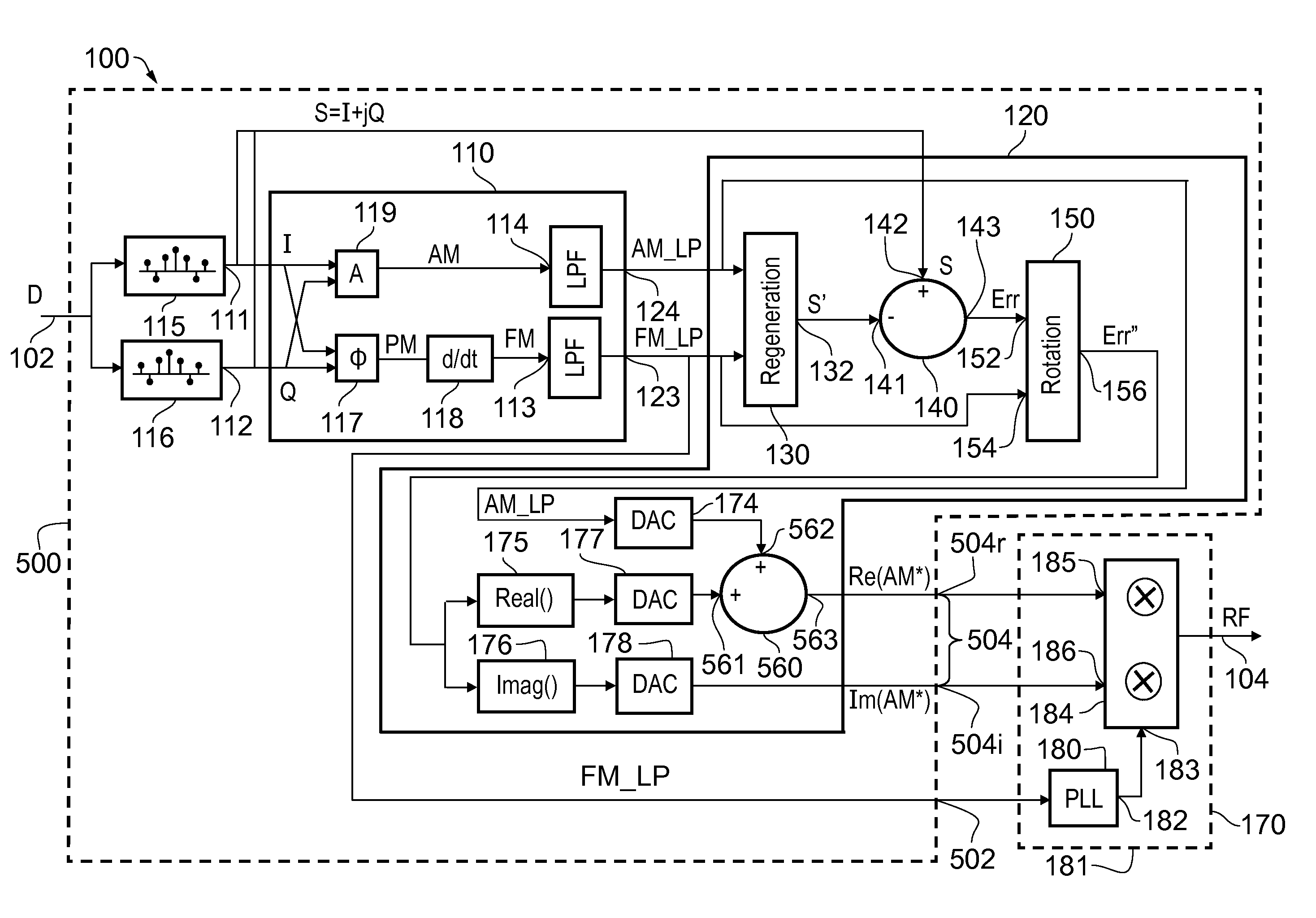
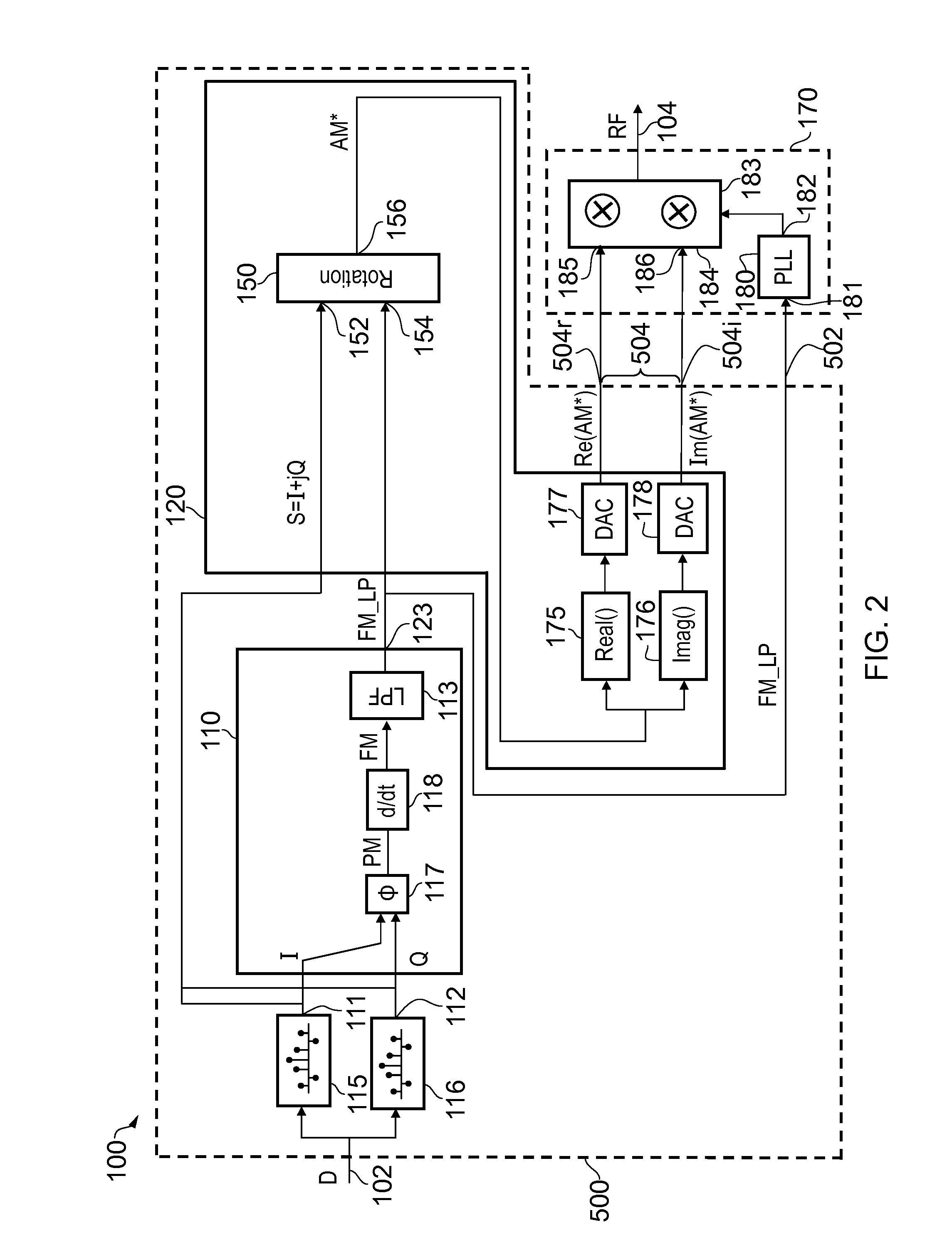
[0008]According to a first aspect there is provided a modulation processor comprising a first processing stage and a second processing stage; wherein the first processing stage comprises:

[0009]a phase generation stage arranged to generate a phase signal indicative of a phase of a modulation signal;

[0010]a differentiation stage arranged to generate a frequency signal by differentiating the phase signal; and

[0011]a first bandwidth reduction stage arranged to generate a first output signal by reducing a bandwidth of the frequency signal; and

wherein the second processing stage is arranged to generate a second output signal proportional to the modulation signal with its phase retarded by an angle equal to an integral of the first output signal.

[0012]According to a second aspect there is provided a method of operating a modulation processor, comprising:

[0013]generating a phase signal indicative of a phase of a modulation signal;

[0014]generating a frequency signal by differentiating the ph...


PUM


Abstract

A modulation processor (500) comprises a first processing stage (110) and a second processing stage (120). The first processing stage (110) comprises a phase generation stage (117) arranged to generate a phase signal (PM) indicative of a phase of a modulation signal (S), a differentiation stage (118) arranged to generate a frequency signal (FM) by differentiating the phase signal (PM), and a first bandwidth reduction stage (113) arranged to generate a first output signal (FM_LP) by reducing a bandwidth of the frequency signal (FM). The second processing stage (120) is arranged to generate a second output signal (AM*) proportional to the modulation signal (S) with its phase retarded by an angle equal to an integral of the first output signal (FM_LP).

Description

FIELD OF THE DISCLOSURE[0001]The present disclosure relates to a modulation processor, a modulator comprising the modulation processor, a transmitter comprising the modulator, a wireless communication device comprising the transmitter, a method of operating a modulation processor, a computer program code arranged to perform the method of operating a modulation processor, and a method of operating a modulator.BACKGROUND TO THE DISCLOSURE[0002]The polar modulator is a good architecture for a radio transmitter when moving to more digitally intensive implementations. A transmitter for the Global System for Mobile Communications (GSM) and for Enhanced Data rates for GSM Evolution (EDGE), and comprising a polar modulator, is disclosed in “Spur-free all-digital PLL in 65 nm for Mobile Phones”, B. Staszewski et al, IEEE International Solid State Circuits Conference, session 3.1, 2011. A transmitter for Wideband Code Division Multiple Access (WCDMA), and comprising a polar modulator, is disc...

Claims


Application Information

Patent Timeline
Patent Type & Authority Patents(United States)
IPC IPC(8): H04L27/36
CPCH04L27/361
Inventor NILSSON, MAGNUSVILHONEN, SAMI
Owner TELEFON AB LM ERICSSON (PUBL)
Why Eureka
Try Eureka