Treatment chamber for treating surgical or dental instruments with electrical energy using chamber wall made of thin film or thick film

a technology of electrical energy and treatment chamber, which is applied in the direction of diagnostics, applications, and diseases, can solve the problems of thermal loss, associated transfer of heat generated, and arrangement of plurality of heating devices and/or heating elements, and achieves simple and easy repair of defective heating elements. , the effect of eliminating thermal loss

Active Publication Date: 2016-12-20
W&H DENTALWERK
View PDF7 Cites 5 Cited by
  • Summary
  • Abstract
  • Description
  • Claims
  • Application Information

AI Technical Summary

Benefits of technology

[0029]One advantage of the present invention is the possibility of generating the required thermal energy directly on and / or through the treatment chamber or the treatment carrier itself. It is no longer necessary to transfer the quantities of heat thereby generated from a separate and independent heating device and / or heating element to the treatment chamber. This eliminates the thermal losses associated with such a transfer.
[0030]Another advantage of the invention is the possibility of designing the treatment chamber or the treatment carrier independently of the heating element. Due to the arrangement of the conductor for converting electrical energy into thermal energy directly on the chamber or the carrier, it is possible to design the shape of the housing in any desired manner, in particular to adapt it to the shape of the medical instrument to be treated.
[0031]In addition, designing the at least one conductor using a coating method, in particular a thin-film or a thick-film method, constitutes an advantage. The design of the at least one conductor as a thin film or a thick film makes it possible to heat the conductor, in particular the treatment chamber or the treatment carrier rapidly, because of the small mass of the layer.
[0032]The possibility of a user-friendly design of the treatment devices constitutes another advantage of the invention. Due to the design of the treatment chamber or the treatment carrier with a conductor made of an electrically conductive material for converting electrical energy into thermal energy, it is possible to generate the thermal energy directly on the treatment chamber. Heating equipment and / or heating elements and connecting lines installed separately are no longer needed. This permits optimization of the construction size of the treatment device, in particular its housing.
[0033]The mounting of an additional conductor, a second or third conductor, in particular a replacement conductor, which is put into operation only when there is a defect in the first or second conductor, additionally permits a simple and easy repair of a defective heating element of the treatment device.

Problems solved by technology

One disadvantage of these embodiments of the treatment devices has proven to be the arrangement of the plurality of heating devices and / or heating elements, in particular as independent units, in the treatment devices.
However, this transfer of the quantities of heat generated is associated with disadvantages.
In particular, the transmission of the operating media from the heating devices to the treatment chambers by means of fluid lines or media lines results in thermal losses.
In addition, the coupling of the independent heating elements to the treatment chambers constitutes a problem.
However, the chambers themselves are preferably adapted to the shape of the medical instruments to be treated and therefore have complex shapes in some cases, which makes the coupling of the heating elements to the treatment chambers difficult.
Another disadvantage is the need for space in the treatment devices for the plurality of heating devices and / or heating elements as well as their connecting lines to the treatment chambers.
This in turn interferes with a user-friendly design of the treatment devices, in particular with a space-saving design of the devices.
Other disadvantage is the high cost of the numerous components, in particular for heating the operating media, for thermally insulated transport of the media and for preheating the treatment chambers.

Method used


Image

  • Treatment chamber for treating surgical or dental instruments with electrical energy using chamber wall made of thin film or thick film
  • Treatment chamber for treating surgical or dental instruments with electrical energy using chamber wall made of thin film or thick film
  • Treatment chamber for treating surgical or dental instruments with electrical energy using chamber wall made of thin film or thick film

Examples


Embodiment Construction

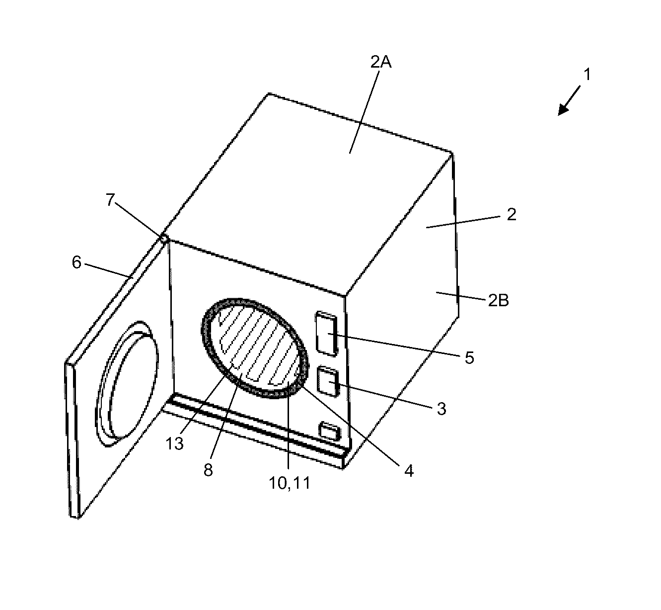
[0040]FIG. 1 shows a first exemplary embodiment of a treatment device 1 for treating at least one medical, in particular dental, instrument. It is preferably designed in the form of a sterilizer 1, in particular a steam sterilizer. The sterilizer 1 comprises a housing 2 having a plurality of exterior walls 2A, 2B. An exterior wall, in particular a side wall, preferably forms the operating side of the cleaning or care device 1. It has a plurality of operating elements 3, which preferably serve to select various operating programs or to set operating parameters. A display screen 5 displays the selected operating programs or parameters of the selected treatment process. In addition to the operating elements 3, the housing 2 of the sterilizer 1 has an opening 4 that is connected to a treatment chamber 8 of the sterilizer 1. An instrument to be treated or a treatment carrier for the at least one medical instrument can be introduced into or removed from the treatment chamber 8 through the...


PUM

PropertyMeasurementUnit
electrical energyaaaaaaaaaa
thermal energyaaaaaaaaaa
distancesaaaaaaaaaa

Abstract

A treatment chamber or treatment carrier for use in a device for treating a medical or dental instrument. The device comprises a housing, which at least partially surrounds the instrument. The device also comprises at least one conductor made of an electrically conductive material layer applied to the housing for converting electrical energy into thermal energy, and at least two electrical contacts embedded in the conductor for supplying the at least one conductor with electrical energy. A treatment device having such a treatment chamber and / or such a treatment carrier is also described.

Description

CROSS REFERENCE TO RELATED APPLICATION[0001]This is a Continuation of International Application No. PCT / EP2013 / 077271, filed Dec. 19, 2013, which was published in German under PCT Article 21(2), which in turn claims the benefit of pending European Patent Application No. 12198313.4, filed Dec. 20, 2012, which are incorporated herein by reference.BACKGROUND[0002]Field[0003]This application relates to a treatment chamber or a treatment carrier for use in a device for treating at least one medical or dental instrument, as well as a treatment device having such a treatment chamber and / or such a treatment carrier.[0004]Description of Prior Art[0005]Treatment devices are used for cleaning, disinfecting, sterilizing and / or caring of medical, in particular dental, instruments. Instruments to be treated are understood in particular to include straight, curved or pistol-shaped handpieces as well as parts of handpieces, e.g., handpiece heads having a tool receptacle for receiving a treatment to...

Claims


Application Information

Patent Timeline
Patent Type & Authority Patents(United States)
IPC IPC(8): A61L2/00B08B3/04B08B3/00A61L2/16A61L2/07A61C19/00
CPCA61B90/70A61C19/002A61L2/07A61L2/16A61C2204/005A61B90/98
Inventor WIMMER, STEFAN
Owner W&H DENTALWERK
Why Eureka
Try Eureka