Unit, assembly and apparatus for treating fluid

a technology for treating fluids and fluids, applied in the direction of multi-stage water/sewage treatment, filtration separation, separation processes, etc., can solve the problem that the treatment medium may also fill up the whole chamber

Active Publication Date: 2016-12-27
CHAU YIU CHAU
View PDF21 Cites 26 Cited by
  • Summary
  • Abstract
  • Description
  • Claims
  • Application Information

AI Technical Summary

Benefits of technology

[0008]In such fluid treatment unit, the fluid to be treated flows through the chamber of the fluid treatment unit from bottom to top; at this time, a treatment medium in the chamber, which is generally granular, shows an upward irregular movement trend as a whole under the action of impact and collides with one another so as to efficiently clean the dirt adhering to the medium itself. In this way, it effectively guarantees that the surface of the treatment medium particles can be in direct contact with and get rid of some chemical substances in the fluid. Since there is no dirt filling in the gaps between the medium particles, the fluid can smoothly flow through these medium particles without generation of a larger pressure drop. Additionally, as the treatment medium particles show an upward movement trend under the action of the fluid flowing from bottom to top, the medium particles are evenly distributed in the chamber of the treatment unit and have a uniform thickness, so that the fluid can be treated uniformly. Generally, the treatment medium in the treatment unit will not fill up a whole chamber of the treatment unit. This on one hand provides a sufficient space for movement of the treatment medium, and on the other hand can avoid a pressure drop before and after the water passing though the treatment unit being too large. However, if necessary, the treatment medium may also fill up the whole chamber.

Problems solved by technology

However, if necessary, the treatment medium may also fill up the whole chamber.

Method used


Image

  • Unit, assembly and apparatus for treating fluid
  • Unit, assembly and apparatus for treating fluid
  • Unit, assembly and apparatus for treating fluid

Examples


first embodiment

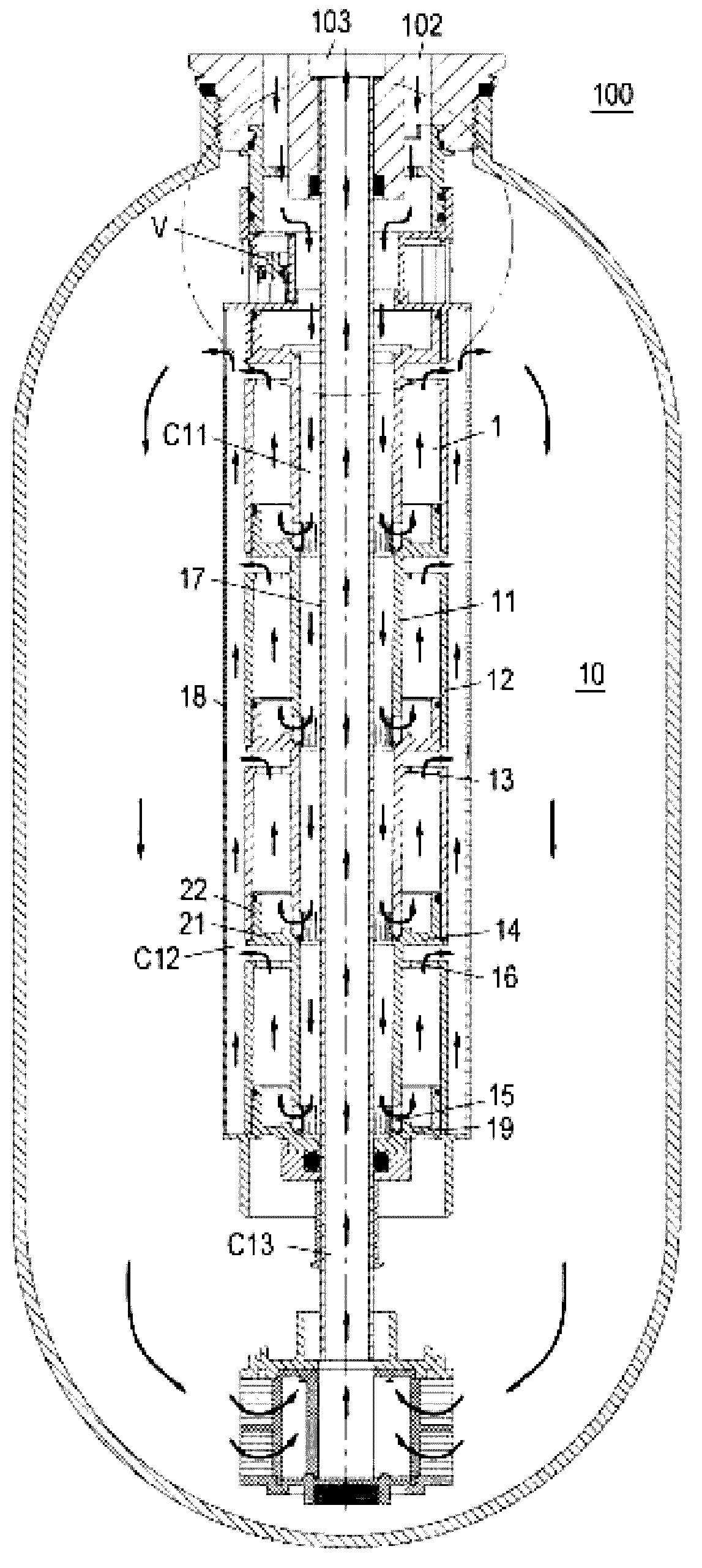
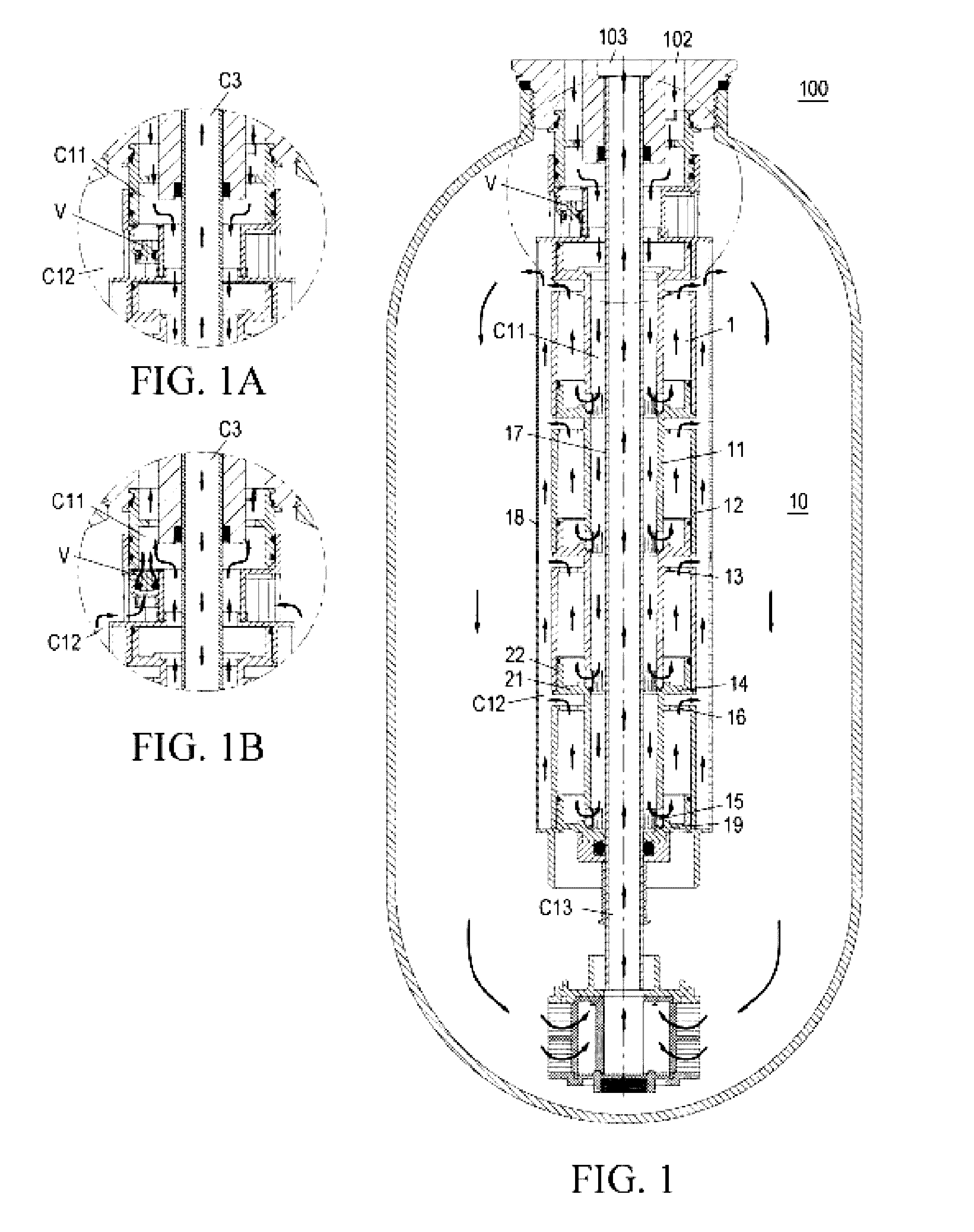
[0035]FIG. 1 is a schematic sectional view of the water treatment device according to the present invention. The water treatment device of the present invention is represented by a reference numeral 100 as a whole. The device generally comprises an elongated tank body 101 accommodating a treatment assembly 10 consisting of a plurality of vertically stacked treatment units 1 and fine grinding fluid treatment mediums stacked in the tank body and so on. The tank body further comprises an opening at the top thereof, and a control unit is mounted at the opening. The control unit conventionally comprises a control valve (not shown) for introduction of the water into the tank body for the convenience of treatment and discharge of the treated water when the device is in normal operation. The control unit generally further comprises a timing mechanism that backwashes the device so as to be convenient for regeneration and / or washing, or other mechanisms (not shown). The opening of the tank bo...

fifth embodiment

[0053]FIG. 5 is a schematic view of the fluid treatment device according to the present invention. The configurations in this embodiment the same as those in previous embodiments are not repeatedly described herein.

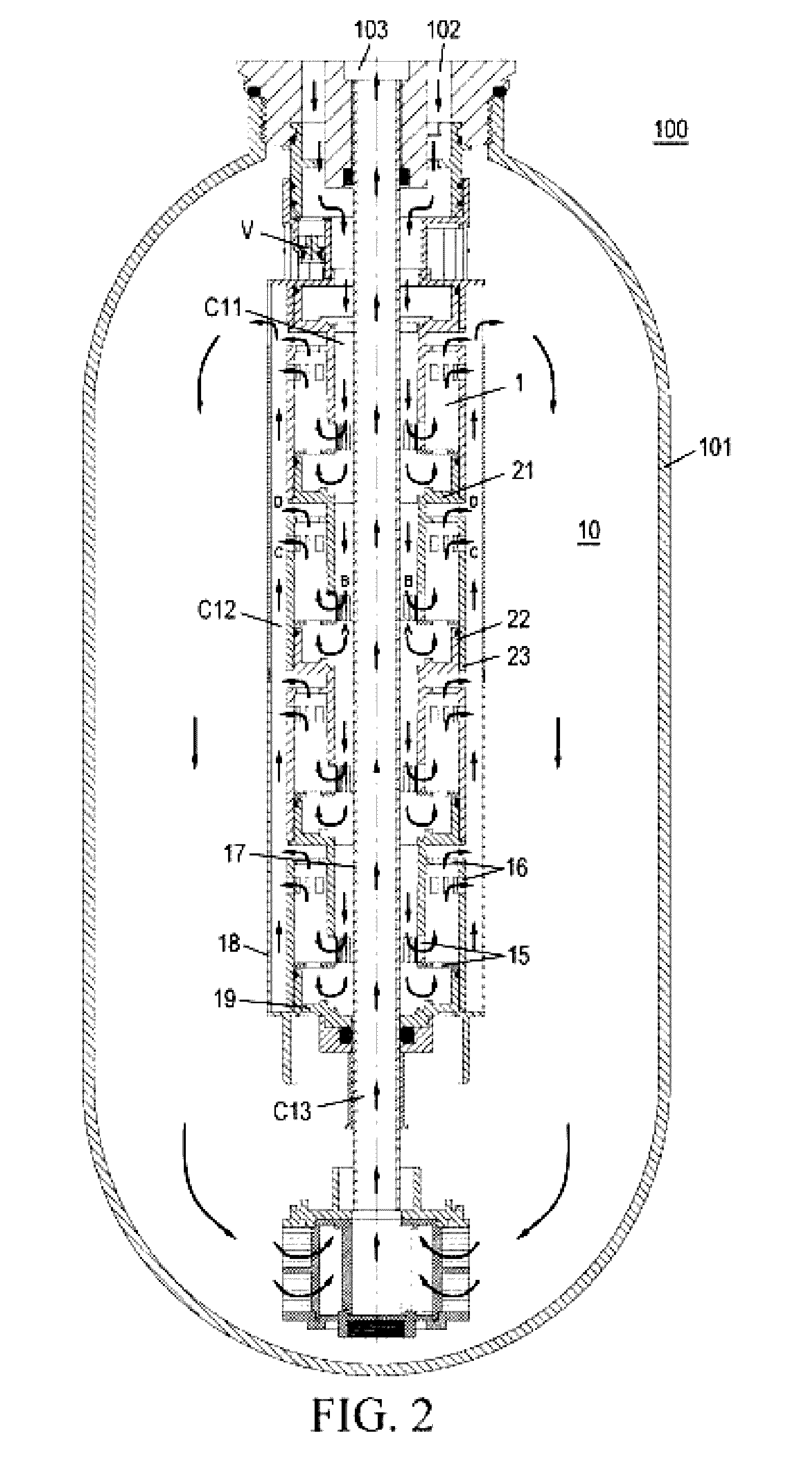
[0054]As shown in the drawing, the treatment assembly in this embodiment exemplarily includes four treatment units, wherein a bottom of an inner wall 11 of the lowermost treatment unit is sealed. The treatment unit merely comprises an outer cylinder but without an inner cylinder. As indicated by the arrows in the drawing, water flow enters into the tank body from the annular introduction inlet 102, and sequentially flows through the first passage between the outer cylinder and the tank body, the fine grinding fluid treatment medium which is preferably provided in the tank body, a second passage between the outer cylinder and the outer walls 12 of the vertically stacked respective treatment units, each treatment unit, a third passage formed by the inner cylinders of respec...

sixth embodiment

[0058]FIG. 6 is a schematic view of the fluid treatment device according to the present invention.

[0059]In the fluid treatment device according to this embodiment, a group of treatment assemblies consisting of two treatment assemblies are arranged in a stacked and series connection manner, and the fine grinding fluid treatment medium is optionally provided in the tank body below the group of the treatment assemblies. The upper treatment assembly is substantially the same as the treatment assembly as shown in FIG. 1, and same contents are not repeatedly described herein; the lower treatment assembly is substantially the same as the treatment assembly as shown in FIG. 3, and same contents are not repeatedly described herein either. Herein, the upper and lower treatment assemblies share the same axis (i.e., the cylinder axis of respective treatment units), the stacked two treatment assemblies as a whole are in an elongated shape, which is suitable for being placed in an elongated tank ...


PUM

PropertyMeasurementUnit
inclined angleaaaaaaaaaa
heightaaaaaaaaaa
widthaaaaaaaaaa

Abstract

A fluid treatment unit (1) is provided. The fluid treatment unit (1) comprises a chamber, in which at least one fine grinding fluid treatment medium is accommodated. The chamber has an inlet (15) for introduction of a fluid to be treated and an outlet (16) for discharge of a treated fluid. The inlet (15) is provided at a lower portion of the chamber and the outlet (16) is provided at an upper portion of the chamber. A fluid treatment device (100) adopting the above fluid treatment unit (1) is also provided. The fluid treatment unit (1) and the fluid treatment device (100) enable the fluid treatment medium to be self-cleaned and the fluid to be treated uniformly.

Description

FIELD OF THE INVENTION[0001]The present invention relates to a fluid treatment unit, and a fluid treatment assembly and a fluid treatment device that employ the fluid treatment unit.BACKGROUND OF THE INVENTION[0002]A fluid treatment device generally uses one or several fluid treatment mediums to treat various fluids, such as water and so on, and generally contains one or more fluid treatment units accommodating the fluid treatment mediums. When fluid passes through a fluid treatment medium, the impurities and pollutant contained therein are removed by physical-chemical reaction with the treatment mediums. A typical example of such fluid treatment device is a device for purifying and softening water. By this device, on one hand, chemical pollutants, such as chlorine, heavy metals and sulfides, particle pollutants and the like in water are removed; and on the other hand, the water is softened due to removing calcium and magnesium in water. Such water treatment device may provide purif...

Claims


Application Information

Patent Timeline
Patent Type & Authority Patents(United States)
IPC IPC(8): B01D24/00B01D24/40B01D24/14B01D24/48B01D24/46C02F1/00B01J47/02C02F1/42C02F1/28
CPCB01D24/00B01D24/14B01D24/40B01D24/4631C02F1/004B01J47/026C02F1/283C02F1/42
Inventor CHAU, YIU CHAU
Owner CHAU YIU CHAU
Why Eureka
Try Eureka