Three-dimensional image processing apparatus, three-dimensional image processing method, three-dimensional image processing program, computer-readable recording medium, and recording device

a three-dimensional image and processing method technology, applied in image analysis, image enhancement, instruments, etc., can solve the problems of increasing the load of data communication, the time required for data transfer is longer, and the difficulty of stably detecting a three-dimensional shape, etc., to achieve the effect of reducing the load of data transfer

Active Publication Date: 2017-01-03
KEYENCE
View PDF8 Cites 3 Cited by
  • Summary
  • Abstract
  • Description
  • Claims
  • Application Information

AI Technical Summary

Benefits of technology

[0013]The present invention is for solving the conventional problems as described above. A principal object of the present invention is to provide a three-dimensional image processing apparatus, a head section for a three-dimensional image processing apparatus, and a three-dimensional image processing method, each of which alleviates a load of data transfer from a camera head section to a body section.
[0014]For achieving the above object, a three-dimensional image processing apparatus according to one embodiment of the present invention is a three-dimensional image processing apparatus, which includes a head section and a controller section, and is capable of acquiring a distance image that includes height information of an inspection target and also performing image processing based on the distance image. The head section can include: a light projecting part for projecting incident light as structured illumination of a predetermined projection pattern from an oblique direction with respect to an optical axis of a below-described image capturing part; the image capturing part for acquiring reflected light that is projected by the light projecting part and reflected on an inspection target, to capture a plurality of pattern projected images; a distance image generating part capable of generating a distance image based on the plurality of pattern projected images captured in the image capturing part; a head-side storage part for holding the distance image generated in the distance image generating part; and a head-side communication part for transmitting the distance image held in the storage part to the controller section. The controller section can include: a controller-side communication part for communicating with the head-side communication part; and an inspection executing part for executing predetermined inspection processing on the distance image received in the controller-side communication part. With the above configuration, a distance image can be generated on the head section side and hence, as compared with a conventional method for receiving a pattern projected image on the controller section side from the head section to generate a distance image, it is possible to significantly reduce an amount of transferred data to be transmitted from the head section to the controller section side, so as to reduce a load of communication and realize high-speed processing.

Problems solved by technology

For this reason, speaking of the foregoing detection of a crack on the workpiece, the apparatus is good at stably detecting a two-dimensional shape of a cracked portion, but having difficulties in stably detecting a three-dimensional shape of, for example, a depression of a flaw which is not apt to appear in a brightness image.
However, when a large number of image data are transmitted from the head section to the controller section side, a load of data communication increases.
This makes the time required for data transfer longer and thus makes real-time processing difficult to perform.
Besides, high-speed communication is necessary for making communication of a large amount of data performed in a short period of time, thus causing a problem of severe specification requirements in terms of hardware and cost increase.

Method used


Image

  • Three-dimensional image processing apparatus, three-dimensional image processing method, three-dimensional image processing program, computer-readable recording medium, and recording device
  • Three-dimensional image processing apparatus, three-dimensional image processing method, three-dimensional image processing program, computer-readable recording medium, and recording device
  • Three-dimensional image processing apparatus, three-dimensional image processing method, three-dimensional image processing program, computer-readable recording medium, and recording device

Examples


first embodiment

(First Embodiment)

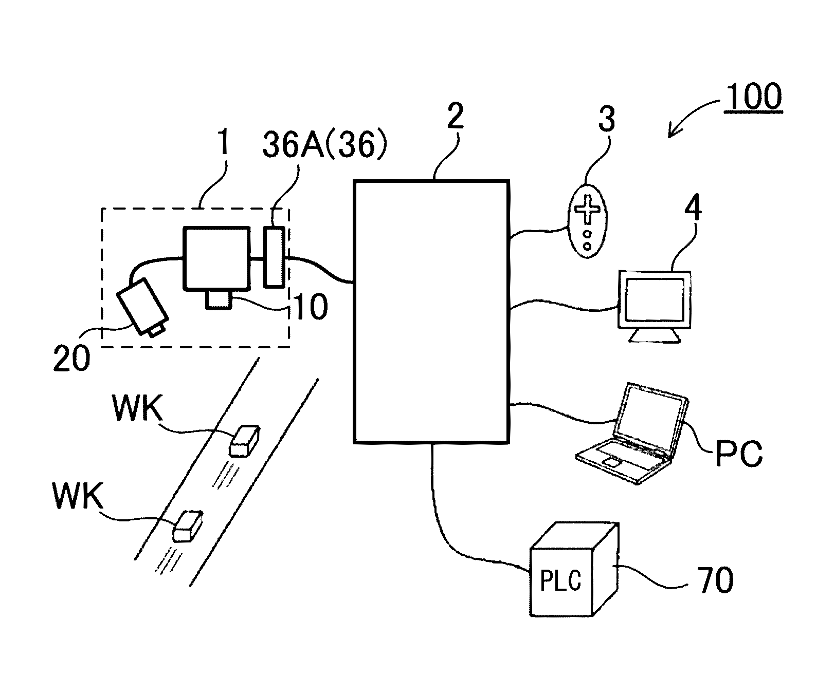
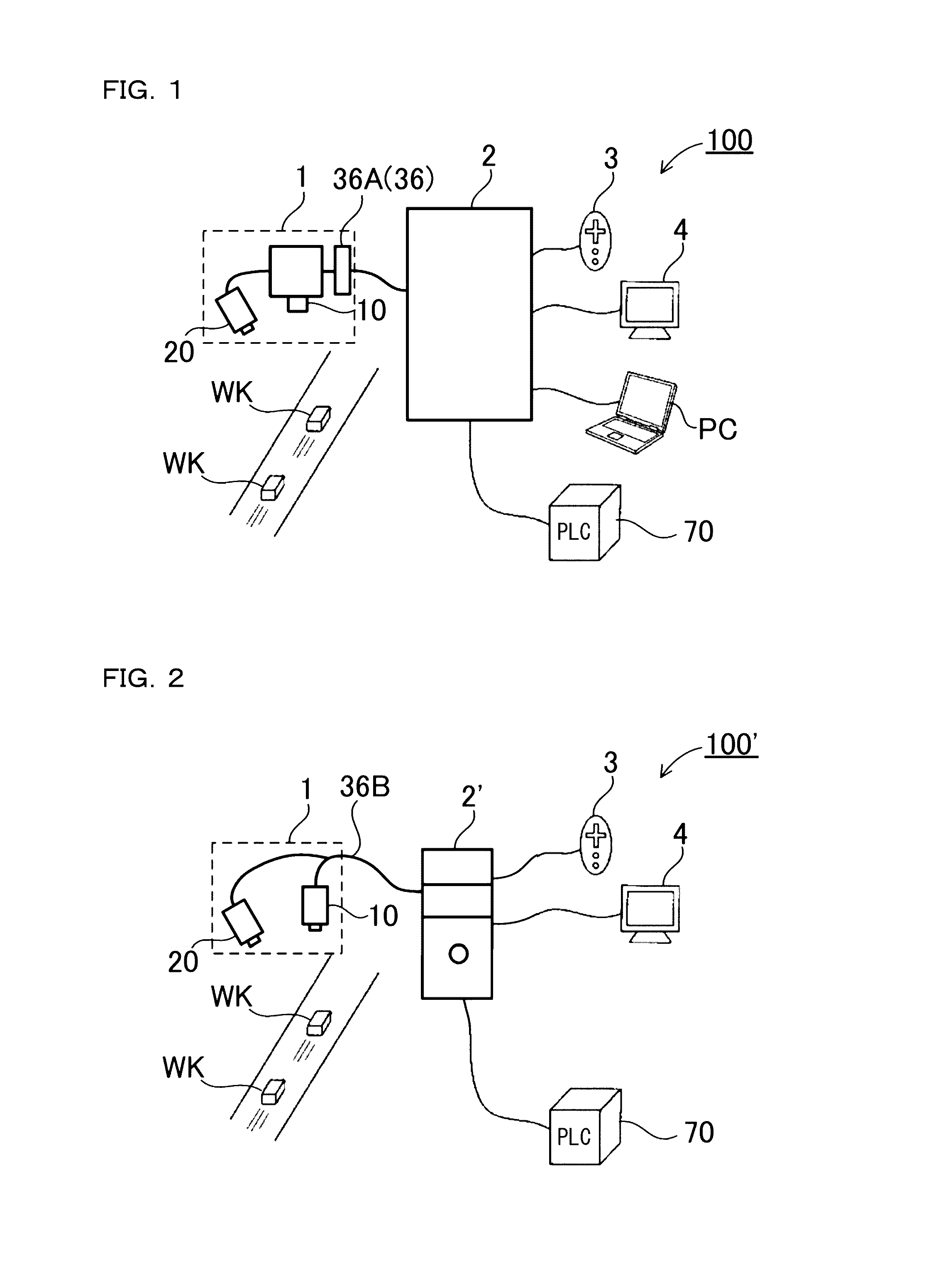
[0198]FIG. 1 shows a configuration of a three-dimensional image processing apparatus according to a first embodiment of the present invention. This three-dimensional image processing apparatus 100 is provided with a head section 1 and a controller section 2. The head section 1 is provided with a light projecting part 20 for illuminating an inspection target (workpiece) W, an image capturing part 10 for capturing an image of the workpiece W, and a head-side communication part 36 for connecting with the controller section 2.

[0199]On the other hand, the controller section 2 executes measurement processing such as edge detection and area calculation based on the captured image. Moreover, the controller section 2 can be detachably connected with a display part 4 such as a liquid crystal panel, an input part 3 such as a console for a user performing a variety of operations on the display part 4, a PLC (Programmable Logic Controller), and the like.

[0200]The above three-di...

second embodiment

(Second Embodiment)

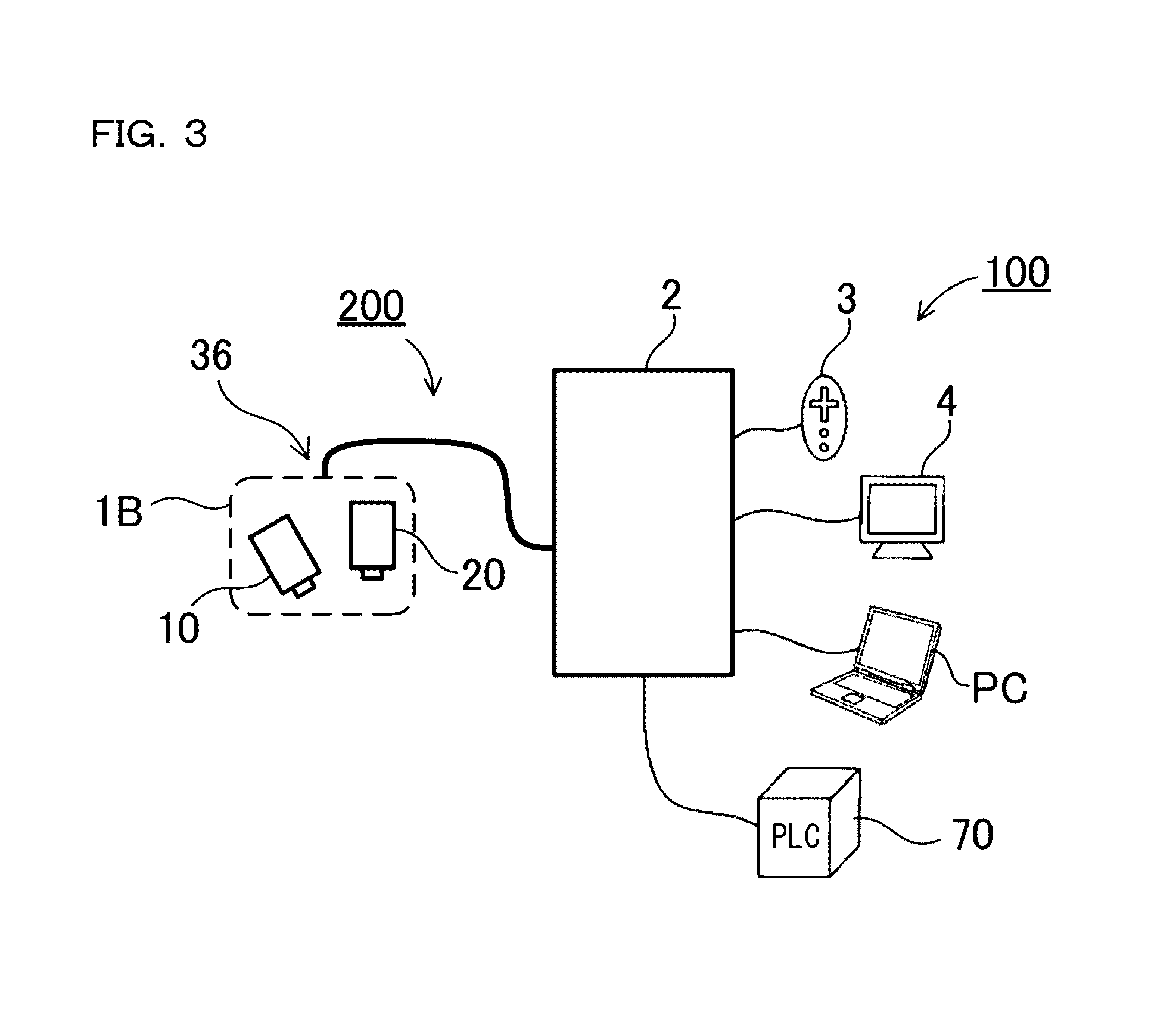
[0215]However, the present invention is not restricted to this disposition example, and for example, as in a three-dimensional image processing apparatus 200 according to a second embodiment shown in FIG. 3, a disposition example may be adopted where the image capturing part 10 side is held obliquely with respect to the workpiece W and the light projecting part 20 side is held vertically. Also by a head section 1B as thus disposed, similarly, it is possible to incline the light projecting direction and the image capturing direction with each other, so as to capture a pattern projected image that has captured the shade of the workpiece W.

third embodiment

(Third Embodiment)

[0216]Further, one of or both the light projecting part and the image capturing part can be disposed in a plurality of number. For example, as in a three-dimensional image processing apparatus 300 shown in FIG. 4A as a third embodiment, while the image capturing part 10 is held vertically with respect to the workpiece W, two light projecting parts 20 are disposed on both sides with the image capturing part 10 placed at the center, which can thus be configured as a head section 1C that projects light from right and left. As thus described, by capturing pattern projected images while projecting light in different directions, it is possible to reduce a situation where the height measurement is inaccurate or impossible due to occurrence of the state of being unable to capture some part of the pattern projected image, such as the state of the workpiece W itself hiding a shade pattern by light projection from one direction. Especially when the light projecting part 20 is...


PUM


Abstract

A head section includes: a light projecting part for projecting incident light as structured illumination of a predetermined projection pattern; the image capturing part for acquiring reflected light that is projected by the light projecting part and reflected on an inspection target, to capture a plurality of pattern projected images; a distance image generating part capable of generating a distance image based on the plurality of pattern projected images captured in the image capturing part; a head-side storage part for holding the distance image generated in the distance image generating part; and a head-side communication part for transmitting the distance image held in the storage part to the controller section. The controller section includes: a controller-side communication part for communicating with the head-side communication part; and an inspection executing part for executing predetermined inspection processing on the distance image received in the controller-side communication part.

Description

CROSS-REFERENCE TO RELATED APPLICATIONS[0001]The present application claims foreign priority based on Japanese Patent Application No. 2013-148064, filed Jul. 16, 2013, the contents of which is incorporated herein by reference.BACKGROUND OF THE INVENTION[0002]1. Field of the Invention[0003]The present invention relates to a three-dimensional image processing apparatus, a three-dimensional image processing method, a three-dimensional image processing program, a computer-readable recording medium, and a recording device.[0004]2. Description of Related Art[0005]In a large number of production sites such as factories, there have been introduced image processing apparatuses that realize automatic and fast performance of inspections, which have relied on viewing of humans. The image processing apparatus captures an image of a workpiece that comes flowing through a production line such as a belt conveyor by use of a camera, and executes measurement processing such as edge detection and area...

Claims


Application Information

Patent Timeline
Patent Type & Authority Patents(United States)
IPC IPC(8): G06T7/00
CPCG06T7/0004G06T7/0057G06T2207/30164G06T7/521
Inventor SAEKI, KAZUHITO
Owner KEYENCE
Why Eureka
Try Eureka