Fastener driving apparatus

a technology of driving apparatus and fastener, which is applied in the direction of nailing tools, manufacturing tools, etc., can solve the problems of large mass differential and unit efficiency, and achieve the effect of sufficient energy

Active Publication Date: 2017-01-10
TRICORD SOLUTIONS
View PDF13 Cites 26 Cited by
  • Summary
  • Abstract
  • Description
  • Claims
  • Application Information

AI Technical Summary

Benefits of technology

[0024]In accordance with the present invention, a fastener driving apparatus is described which derives its power from an electrical source, preferably rechargeable batteries, and uses a motor to actuate a spring (such as a gas spring, for example). After sufficient movement of a piston in the gas spring, the piston of the gas spring commences movement, accelerating an anvil and / or anvil assembly. The anvil assembly preferably has a mass that is greater than the weight of the piston, the contact of the piston with the anvil causes the anvil to move. In an embodiment, the piston comes to rest on a bumper but the anvil assembly continues to move toward and into contact with a fastener such that the anvil drives the fastener. The effective mass differential between the piston and the anvil facilitates sufficient energy being transferred to the anvil for driving a fastener. A return spring or other return mechanism is incorporated to return the anvil, after the anvil drives the fastener, to a position where the anvil and / or anvil assembly may again be operatively contacted by the piston for another drive by the anvil.

Problems solved by technology

This unexpectedly increased the efficiency of the unit since heat of compression of a gas is a significant source of energy inefficiency.
During the inventive process, it was also discovered that the mass differential greatly impacts the efficiency of the device.

Method used


Image

  • Fastener driving apparatus
  • Fastener driving apparatus
  • Fastener driving apparatus

Examples


Embodiment Construction

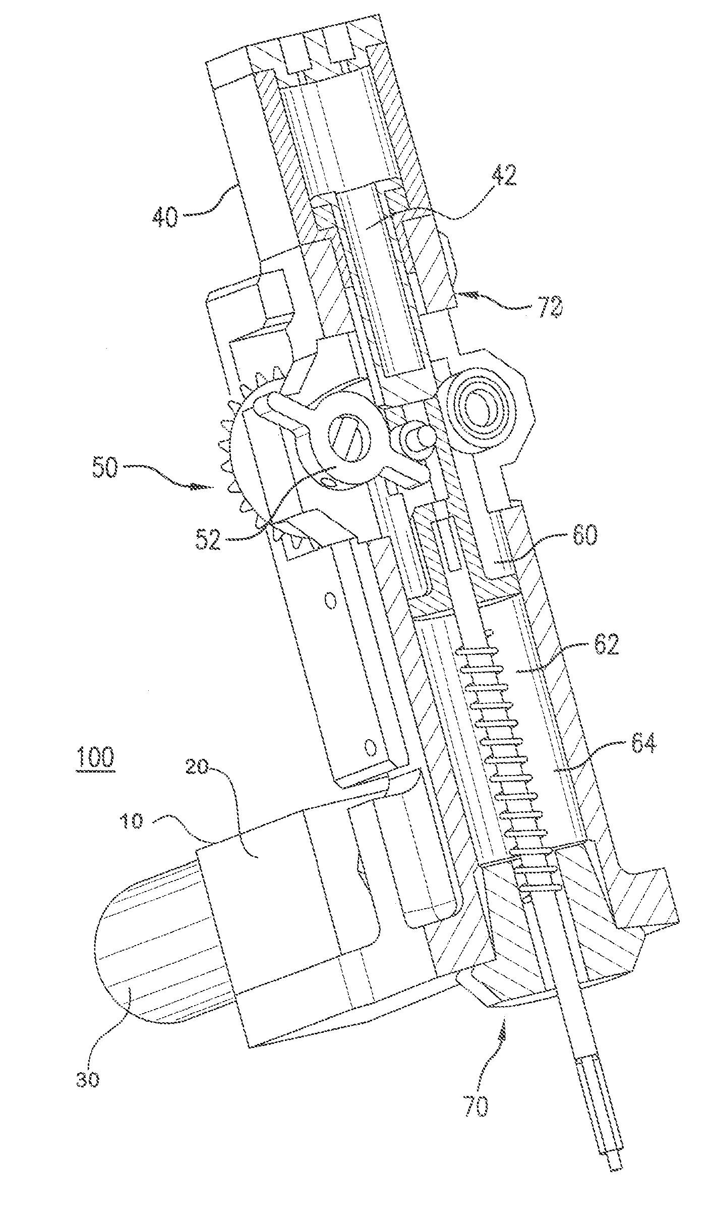
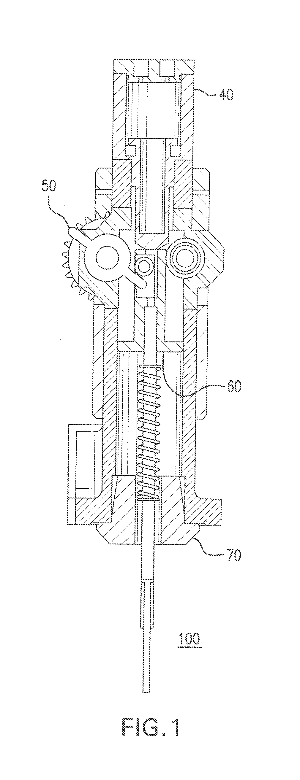
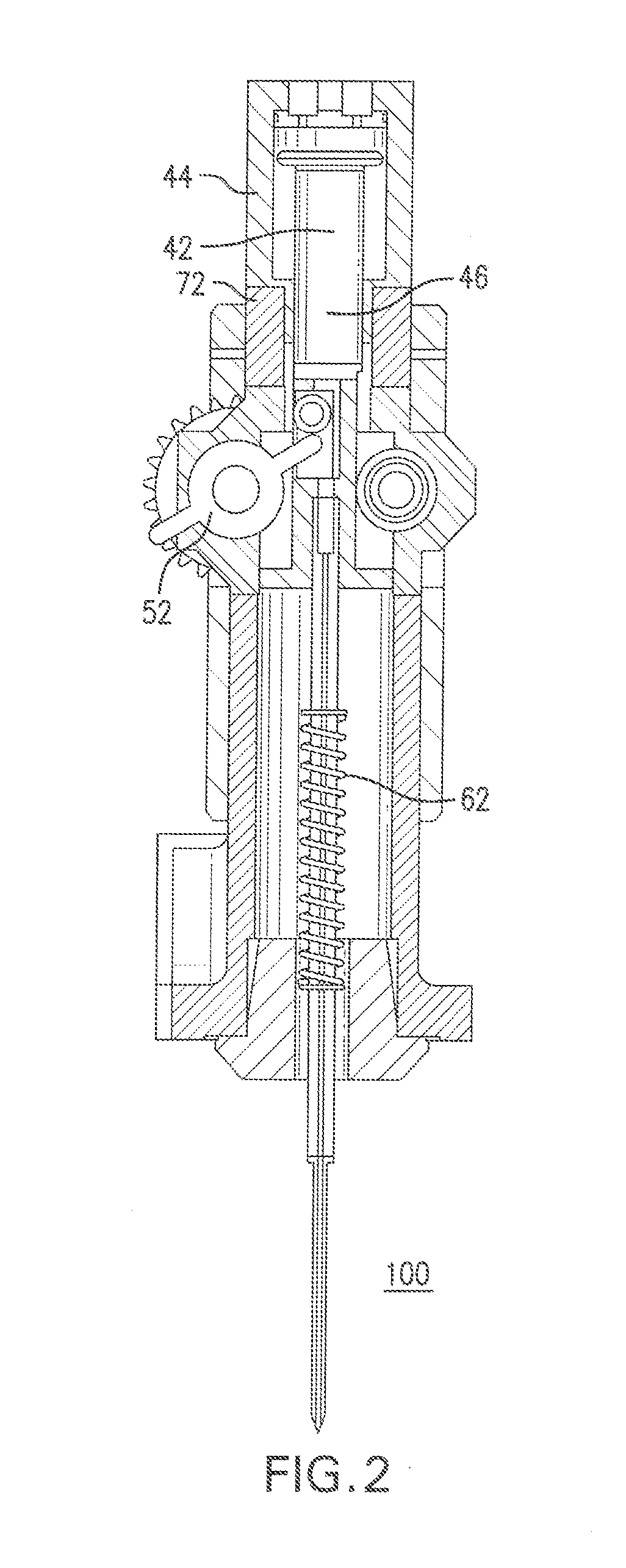
[0046]The best mode for carrying out the present disclosure is presented in terms of its preferred embodiment, herein depicted in the accompanying figures. The preferred embodiments described herein detail for illustrative purposes are subject to many variations. It is understood that various omissions and substitutions of equivalents are contemplated as circumstances may suggest or render expedient, but are intended to cover the application or implementation without departing from the spirit or scope of the present disclosure. Furthermore, although the following relates substantially to one embodiment of the design, it will be understood by those familiar with the art that changes to materials, part descriptions and geometries can be made without departing from the spirit of the invention. It is further understood that references such as front, back or top dead center, bottom dead center do not refer to exact positions but approximate positions as understood in the context of the g...


PUM


Abstract

A fastener driving apparatus comprises a gas spring or spring, a drive mechanism, an anvil assembly, and an anvil. The drive mechanism permits transition from engagement with the gas spring, spring or anvil assembly to disengagement from the gas spring, spring or anvil assembly. The anvil and/or anvil assembly are operatively coupled to the gas spring or spring such that after the drive mechanism disengages them, the gas spring piston or the spring moves to imparts a force on the anvil to cause the anvil to move and drive a fastener. The mass of the anvil assembly is preferably greater than 50% of the total mass of the anvil assembly and gas spring moving mass. The gas spring is configured such that the pressure increase during the movement of the gas spring piston by the drive mechanism is less than 30% of the initial pressure in the gas spring.

Description

CROSS REFERENCE TO RELATED APPLICATIONS[0001]The present disclosure is a continuation-in-part of U.S. Non-provisional patent application Ser. No. 14 / 877,742, filed on Oct. 7, 2015 and also claims priority under 35 United States Code, Section 119 on the U.S. Provisional patent application Ser. No. 62 / 060,690 filed on Oct. 7, 2014, and Ser. No. 62 / 195,850 filed Jul. 23, 2015, the disclosures of which are incorporated by reference.FIELD OF THE DISCLOSURE[0002]The present disclosure relates to fastener driving apparatuses, and, more particularly, to such fastener or staple driving mechanisms that require operation as a hand tool.BACKGROUND[0003]Electromechanical fastener driving apparatuses (also referred to herein as a “driver,”“gun” or “device”) known in the art often weigh generally less than 15 pounds and may be configured for an entirely portable operation. Contractors and homeowners commonly use power-assisted devices and means of driving fasteners into wood. These power-assisted ...

Claims


Application Information

Patent Timeline
Patent Type & Authority Patents(United States)
IPC IPC(8): B25C1/04B25C1/06
CPCB25C1/047B25C1/04B25C1/06
Inventor PEDICINI, CHRISTOPHER
Owner TRICORD SOLUTIONS
Why Eureka
Try Eureka