
Vehicle

a technology for vehicles and arms, applied in the field of vehicles, can solve the problems of difficult layout and imposed arrangement limitations, and achieve the effects of increasing the widthwise length of the vehicle, increasing the arm length, and prolonging the strok

Active Publication Date: 2017-01-10
YAMAHA MOTOR CO LTD
View PDF29 Cites 8 Cited by
  • Summary
  • Abstract
  • Description
  • Claims
  • Application Information

AI Technical Summary

Benefits of technology

[0010]Accordingly, preferred embodiments of the present invention provide a vehicle that includes upper and lower arms having long arm lengths without an increase in the widthwise length of the vehicle, and enables the upper and lower arms to have increased flexibility in terms of mounting positions thereof.
[0013]Various preferred embodiments of the present invention provide a vehicle that includes upper and lower arms with long arm lengths and without an increase in widthwise length of the vehicle, and enables the upper and lower arms to have increased flexibility in terms of mounting positions thereof.

Problems solved by technology

In contrast, if the first and second straight lines incline outward away from the widthwise center of the vehicle as they extend rearward, the first front connector and the second front connector must be disposed inward in the width direction of the vehicle so as not to increase the widthwise length of the vehicle, which makes it difficult to perform the layout of, for example, the engine at least partially disposed inward of the first front connector and the second front connector in the width direction of the vehicle.
If an attempt is made to dispose the first front connector and the second front connector at the same position in a plan view, and dispose the first rear connector and the second rear connector at the same position in the plan view, limitations are also imposed on the arrangement of the second front connector and the second rear connector, which connect the lower arm and the body frame to each other.

Method used


Image

  • Vehicle
  • Vehicle
  • Vehicle

Examples


Embodiment Construction

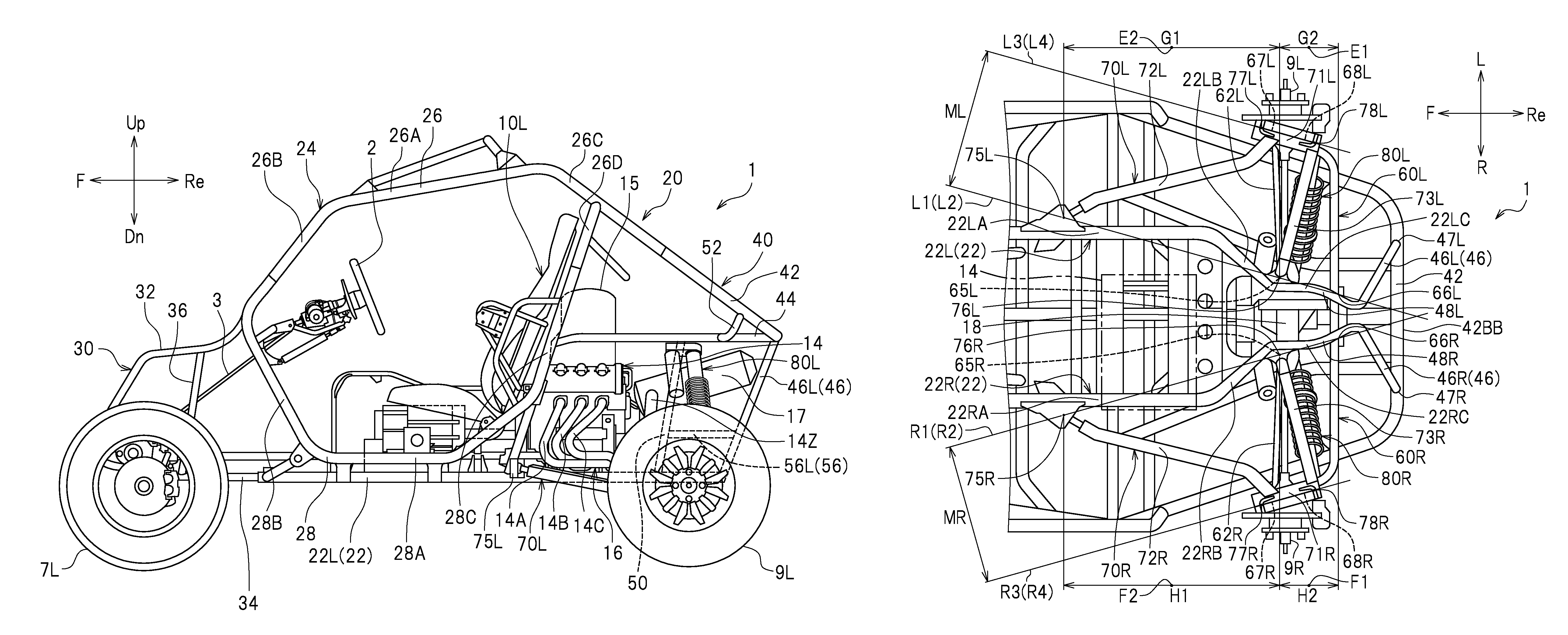
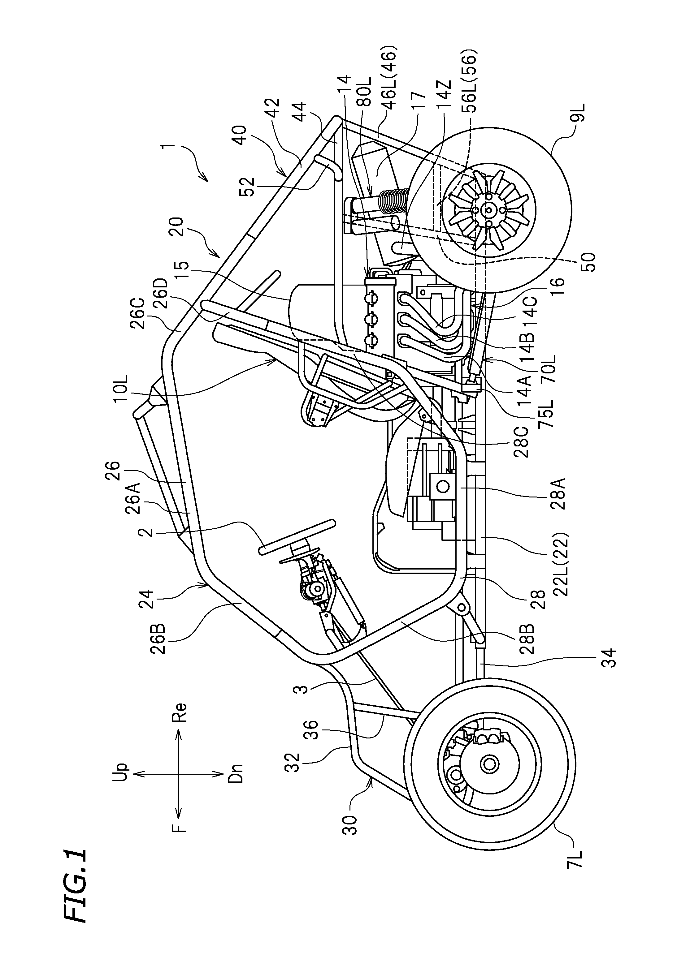
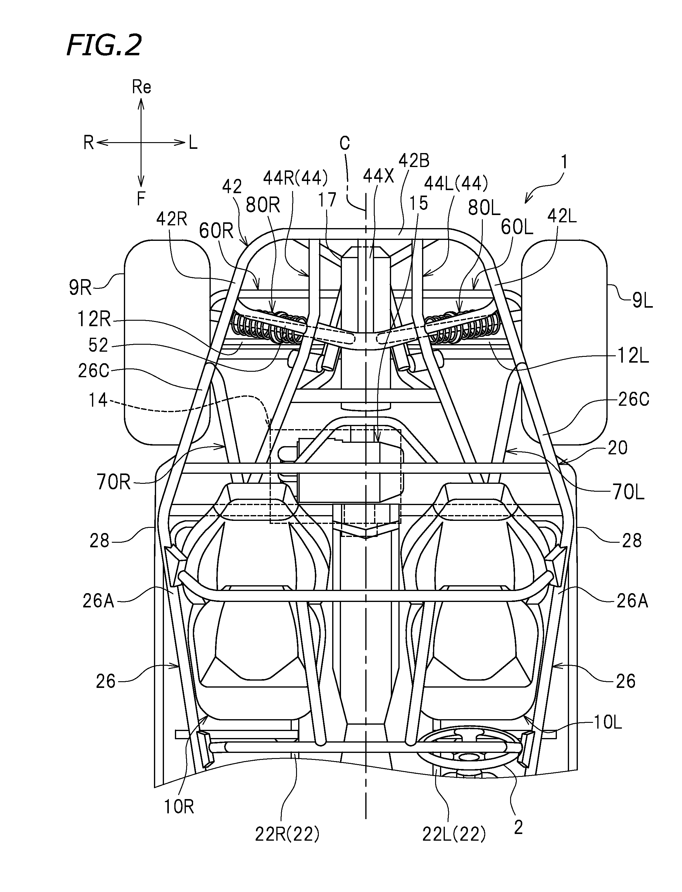
[0024]Hereinafter, preferred embodiments of the present invention will be described. As illustrated in FIG. 1, a vehicle according to the present preferred embodiment is, for example, a recreational off-highway vehicle (ROV) 1. The ROV 1 is suitable for traveling over rough terrain. The vehicle according to the preferred embodiments of the present invention is not limited to an ROV, but may be an all-terrain vehicle (ATV) or other suitable vehicle, for example.

[0025]Unless otherwise noted, the terms “front”, “rear”, “right”, “left”, “up”, and “down” respectively refer to front, rear, right, left, up, and down with respect to a driver sitting on a left seat 10L of the ROV 1 in the following description. The terms “up” and “down” respectively refer to the vertically upward direction and the vertically downward direction when the ROV 1 is stationary on a horizontal plane. Reference signs “F”, “Re”, “R”, “L”, “Up”, and “Dn” in the drawings respectively represent front, rear, right, left...


PUM


Abstract

In a vehicle, a first left straight line, passing through a first left front connector and a first left rear connector connecting a left upper arm and a left auxiliary frame, inclines inward toward a widthwise center as the first left straight line extends rearward in a bottom view. A second left straight line, passing through a second left front connector and a second left rear connector connecting a left lower arm and a left main subframe, inclines inward toward the widthwise center as the second left straight line extends rearward in the bottom view. A central position between the first left front connector and first left rear connector in the front-rear direction is rearward relative to a central position between the second left front connector and second left rear connector in the front-rear direction.

Description

[0001]This application claims priority to Patent Application No. 2014-261978 filed in Japan on Dec. 25, 2014, the entire contents of which are hereby incorporated by reference.BACKGROUND OF THE INVENTION[0002]1. Field of the Invention[0003]The present invention relates to vehicles suitable for traveling over rough terrain.[0004]2. Description of the Related Art[0005]Vehicles suitable for traveling over rough terrain are conventionally known. Included among such vehicles are an all-terrain vehicle (ATV) and a recreational off-highway vehicle (ROV). For example, U.S. Pat. No. 7,461,851 B2 and U.S. Pat. No. 6,695,329 B2 each disclose an ROV including upper arms, lower arms, a body frame, rear wheels, and shock absorbers. The rear wheels are supported by the body frame via the upper and lower arms that are movable members. The shock absorbers are connected to the body frame and the lower arms.[0006]In general, the larger the operating range or stroke of a shock absorber, the greater the...

Claims


Application Information

Patent Timeline
Patent Type & Authority Patents(United States)
IPC IPC(8): B60G3/20B62D23/00B60G7/00B60K5/00B60G13/00
CPCB60G3/20B60G7/001B60G13/005B60K5/00B62D23/005B60K2005/003B60G2200/144B60G2300/124B60G2300/13B60Y2200/124
Inventor SUZUKI, YASUHIROKUBO, MASAYUKI
Owner YAMAHA MOTOR CO LTD
Learn More