
Subsea umbilical

a technology of umbilical cords and submerged cables, applied in the field of umbilical cords, can solve the problems of requiring additional protective sheaths, and affecting etc., and achieves the effects of reducing the service life of the umbilical cord

Active Publication Date: 2017-01-10
TECH FRANCE SA
View PDF23 Cites 2 Cited by
  • Summary
  • Abstract
  • Description
  • Claims
  • Application Information

AI Technical Summary

Benefits of technology

The present invention aims to minimize or overcome the disadvantageous diffusion of hydrogen gas inside electric cables. The solution involves the use of a metallic layer as a barrier against hydrogen gas diffusion, which greatly reduces the amount of hydrogen gas inside the cable and its conductors. Additionally, the protective polymer sheath is bonded to the tubular metallic layer to prevent hydrogen gas from circulating along the cable. These measures improve the hydrogen gas tightness of the cable and enhance its durability.

Problems solved by technology

Indeed, because of their low voltage, such multicore cables are not sensitive to moisture ingress, unlike medium and high voltage coaxial power cables (respectively rated at 6 kV to 30 kV and at more than 30 kV) which are known to be very sensitive to water ingress and may develop detrimental defects known as “water tree”, and therefore require additional protective sheaths to prevent moisture ingress.
A problem with known electric cables within subsea umbilicals is that, over an extended period of time, in some circumstances related to the presence of sea water, small quantities of hydrogen appear inside the umbilical structure, and then diffuse inside the electric cables.
The presence and the circulation of hydrogen gas inside the electric cables have several detrimental effects.

Method used


Image

  • Subsea umbilical
  • Subsea umbilical
  • Subsea umbilical

Examples


first embodiment

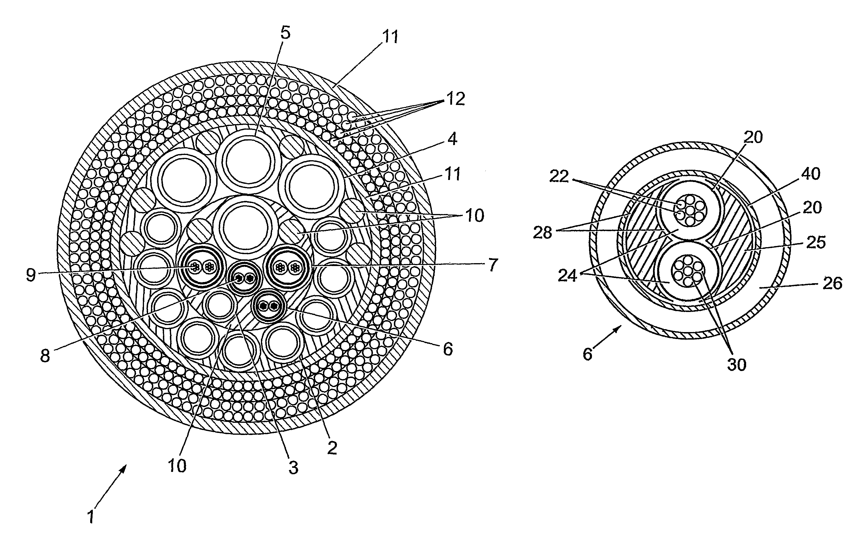
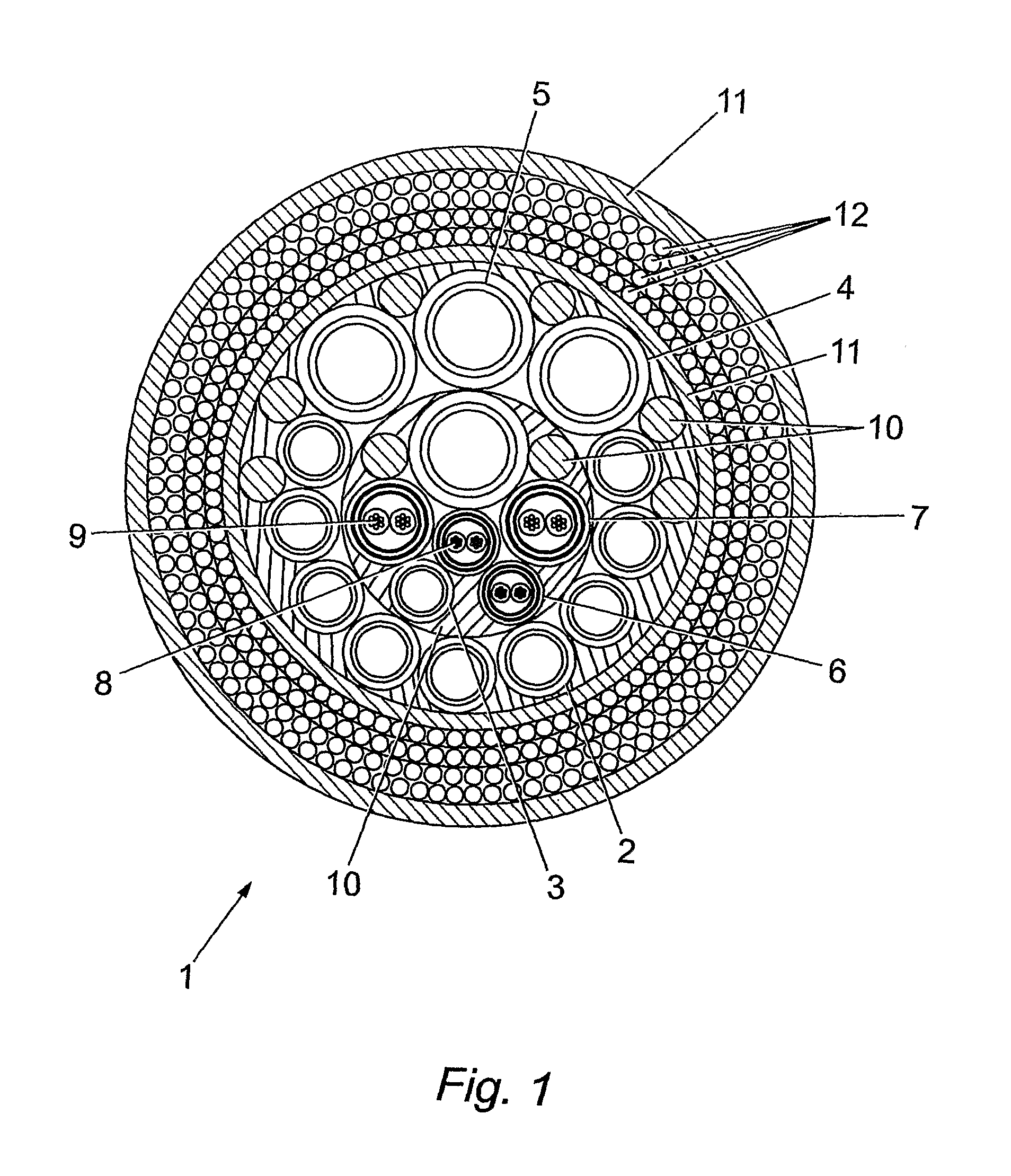
[0022]In the present invention, as illustrated in FIG. 2, each multicore low voltage electric cable 6 comprises two electric conductors 20. However, it is envisaged that the multicore low voltage electric cable may comprise more than two conductors 20, typically three or four conductors. In the example shown, each conductor is made of seven stranded circular copper wires 22. It could also be possible to used solid conductors (according to the IEC 60228 International Standard) without departing from the present invention. Each conductor 20 is sheathed by an electrical insulation polymer sheath 24. Both insulated conductors 20 are assembled in a helical or S / Z manner together with filler material 25 to form a substantially cylindrical core. A copper tubular layer 40 surrounds this cylindrical core and thus both insulated conductors. The copper tubular layer 40 acts as a barrier reducing the hydrogen diffusion from the outside to the inside of the multicore low voltage electric cable 2...

second embodiment

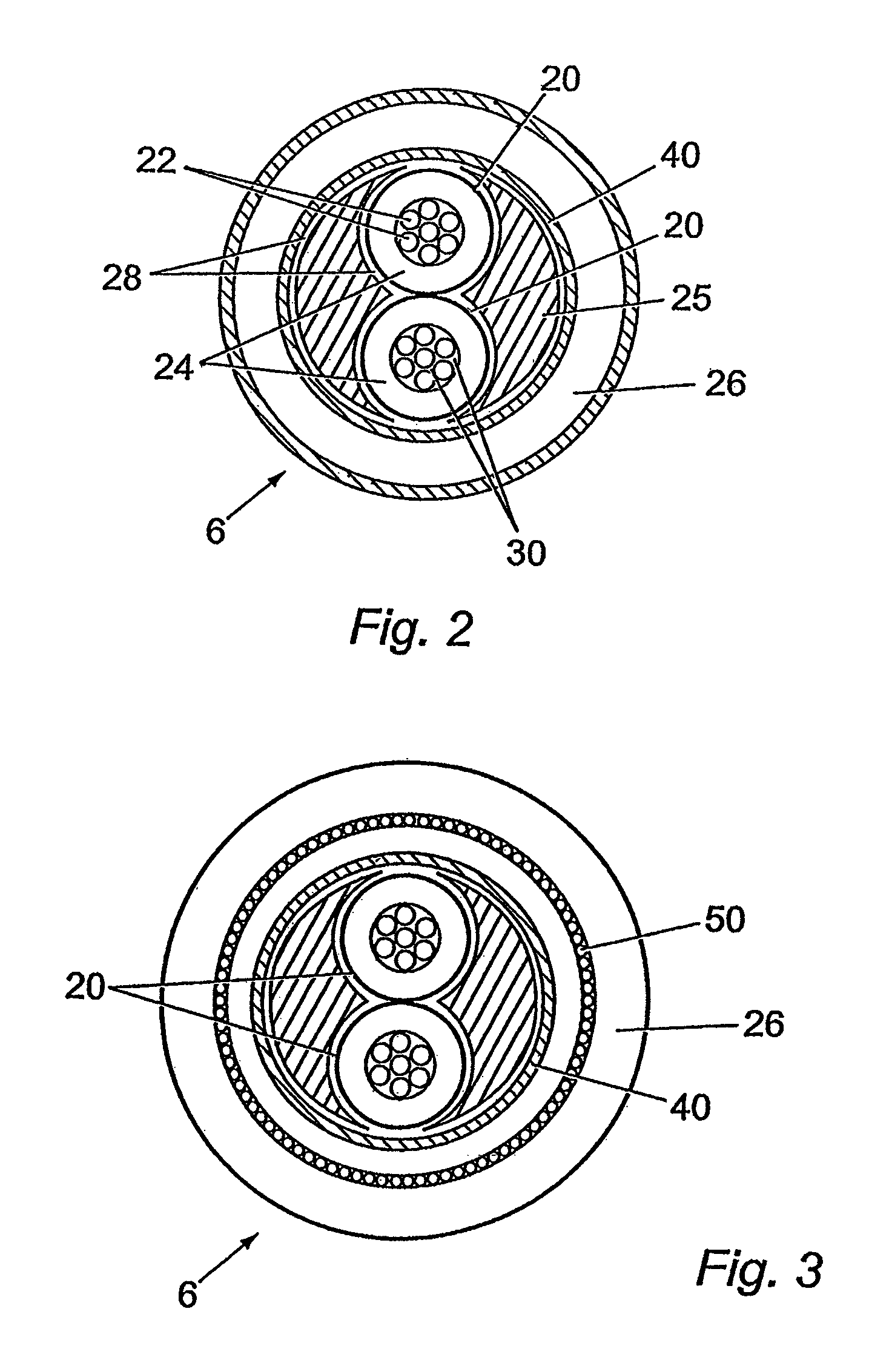
[0027]FIG. 3 shows an electric cable for use in an umbilical according to the present invention. It differs from the previous embodiment by the fact that it comprises armouring wires 50 within the protective polymer sheath 26 for improving the mechanical resistance of the cable 20


PUM

PropertyMeasurementUnit
voltageaaaaaaaaaa
voltageaaaaaaaaaa
voltageaaaaaaaaaa

Abstract

An umbilical for use in the offshore production of hydrocarbons, the umbilical comprising a plurality of functional elements contained within an outer sheath, at least one of said functional elements comprising a multicore electric cable, said multicore electric cable comprising a plurality of insulated electric conductors electrically insulated from each other and assembled together in a helical or S / Z manner, said multicore electric cable further comprising a protective polymer sheath surrounding said plurality of insulated electric conductors, said multicore electric cable further comprising a tubular metallic layer located inside said protective polymer sheath and surrounding said plurality of insulated electric conductors.

Description

CROSS REFERENCE TO RELATED APPLICATIONS[0001]The present application is a 35 U.S.C. §371 National Phase conversion of PCT / GB2007 / 003307, filed Sep. 4, 2007, which claims benefit of British Application No. 0618108.5, filed Sep. 14, 2006, and British Application No. 0711859.9, filed Jun. 20, 2007, the disclosures of which are incorporated herein by reference. The PCT International Application was published in the English language.FIELD OF THE INVENTION[0002]The present invention relates to an umbilical for use in the offshore production of hydrocarbons.BACKGROUND OF THE INVENTION[0003]In subsea oil field operations, umbilicals are used to transport fluids, power, signals or data to and from a subsea installation. An umbilical comprises a group of one or more types of functional elements such as multicore low voltage electric cables, optical fibre cables, or hoses for fluid transportation of, for example, gas, water or chemical products such as methanol. These functional elements are a...

Claims


Application Information

Patent Timeline
Patent Type & Authority Patents(United States)
IPC IPC(8): H01B11/04H01B7/14H01B7/285H01B7/28H01B7/00H01B7/04
CPCH01B7/14H01B7/0072H01B7/045H01B7/285H01B7/2813Y02A30/14H01B13/262H01B13/2633H01B7/2825
Inventor DEIGHTON, ALANWONG, JOE SIU KIT
Owner TECH FRANCE SA
Learn More