Rotating X-ray anode with an at least partly radially aligned ground structure

a technology of x-ray anode and radial alignment, which is applied in the direction of x-ray tube bonding/fixing, electrical discharge tubes, electrical apparatuses, etc., to achieve the effect of suppressing the occurrence of fatigue effects during use and being cheap to produ

Active Publication Date: 2017-01-10
PLANSEE SE
View PDF9 Cites 2 Cited by
  • Summary
  • Abstract
  • Description
  • Claims
  • Application Information

AI Technical Summary

Benefits of technology

[0007]Accordingly, the problem addressed by the present invention is that of providing a rotating x-ray anode that is inexpensive to produce and with which the occurrence of fatigue effects during use can be suppressed as effectively as possible. The problem addressed is also that of providing a corresponding method for producing a rotating x-ray anode.

Problems solved by technology

The problem addressed is also that of providing a corresponding method for producing a rotating x-ray anode.

Method used


Image

  • Rotating X-ray anode with an at least partly radially aligned ground structure
  • Rotating X-ray anode with an at least partly radially aligned ground structure
  • Rotating X-ray anode with an at least partly radially aligned ground structure

Examples


Embodiment Construction

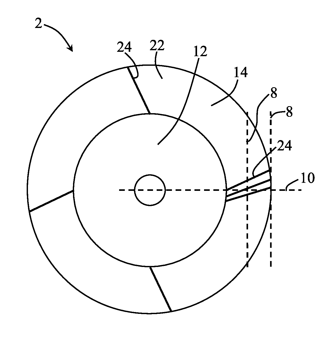
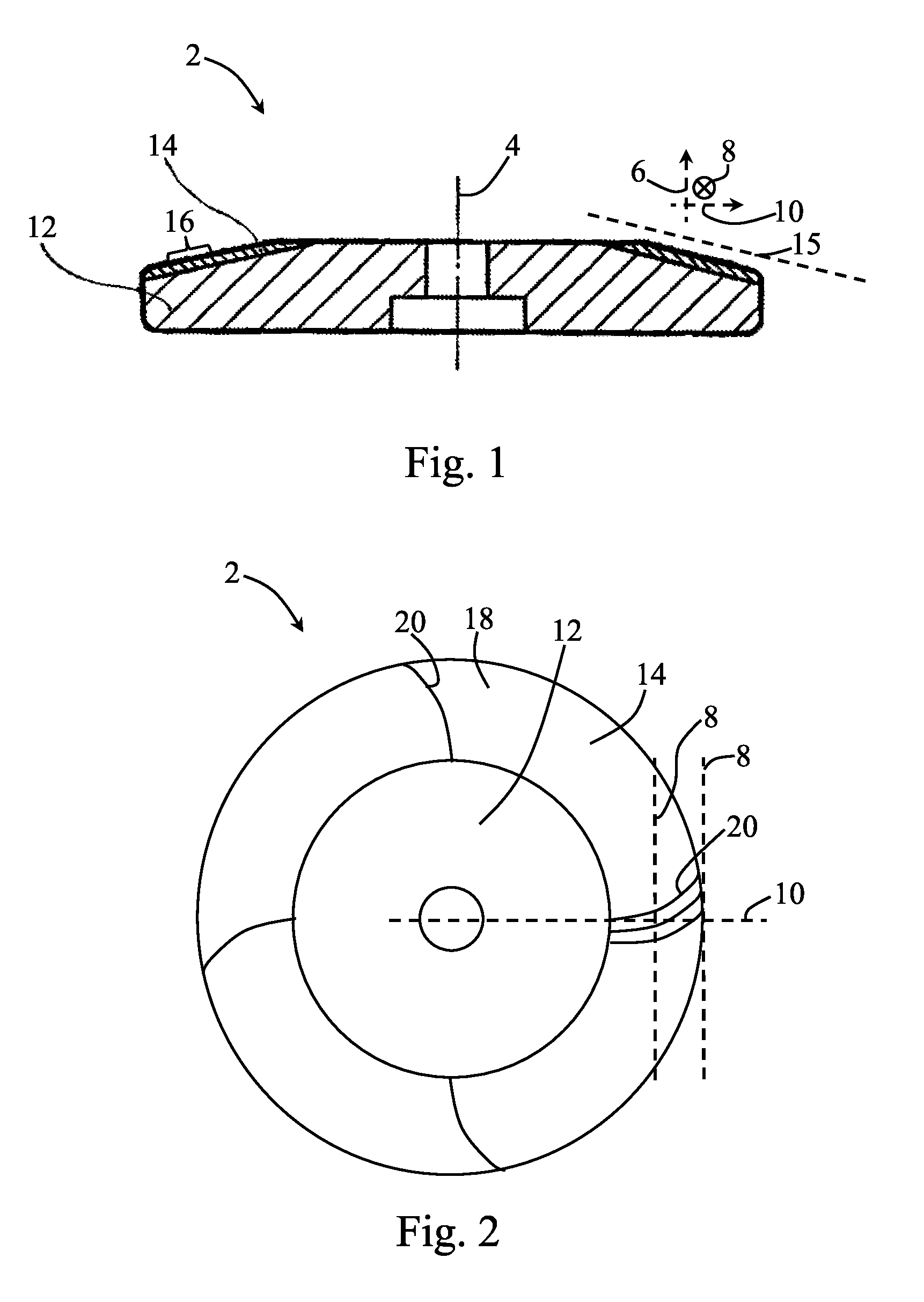
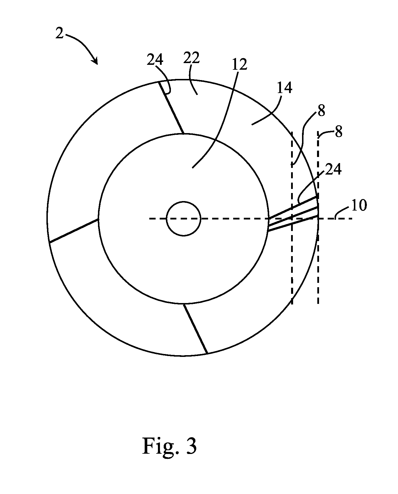
[0034]In FIG. 1, the structure of a rotating x-ray anode -2- is schematically represented. The rotating x-ray anode -2- is formed rotationally symmetrically in relation to an axis of rotational symmetry -4-. Determined at the same time by the axis of rotational symmetry -4- is an axial direction -6-, which respectively runs through the point to be characterized that is concerned and parallel to the axis of rotational symmetry -4-. Running perpendicularly to the axial direction -6- are the tangential direction -8- (depicted in the present case as counter to the clockwise direction), which respectively forms a tangent to the circumference at the point concerned, and the radial direction -10-, which is perpendicular to the tangential direction -8- and the axial direction -6-. The rotating x-ray anode -2- has a disk-shaped carrier body -12-, which can be mounted on a corresponding shaft. Applied to the carrier body -12- on the top side is an annular focal track layer -14-. The portion o...


PUM


Abstract

A rotating x-ray anode has an annular focal track. The surface of the focal track has a directed ground structure. Over the circumference of the annular focal track and over the radial extent of the focal track, the alignment of the ground structure is inclined relative to a tangential reference direction in the respective surface portion in each case by an angle that lies in the range from 15°, including, up to and including 90°. A corresponding method for producing a rotating x-ray anode is described.

Description

BACKGROUND OF THE INVENTIONField of the Invention[0001]The present invention relates to a rotating x-ray anode with an annular focal track, the surface of the focal track having a directed ground structure.[0002]Rotating x-ray anodes are used in x-ray tubes for generating x-ray beams. X-ray machines with such rotating x-ray anodes are used in particular in the medical sector, in the area of imaging diagnostics. During use, electrons are emitted from a cathode of the x-ray tube and accelerated in the form of a focused electron beam onto the rotating x-ray anode that has been set in rotation. A large part of the energy of the electron beam is converted into heat in the rotating x-ray anode, while a small proportion is radiated as x-radiation. The locally released amounts of heat lead to strong heating up of the rotating x-ray anode.[0003]On account of the rotary movement of the rotating x-ray anode, an annular track (focal track) is scanned by the electron beam during use. Rotating x-...

Claims


Application Information

Patent Timeline
Patent Type & Authority Patents(United States)
IPC IPC(8): H01J35/10H01J9/14
CPCH01J35/101H01J9/14H01J35/10H01J2235/083H01J2235/085H01J2235/1006
Inventor ROEDHAMMER, PETERSCHATTE, JUERGENGLATZ, WOLFGANGMUELLER, THOMAS
Owner PLANSEE SE
Why Eureka
Try Eureka