
Advanced electrolyte systems and their use in energy storage devices

a technology of advanced electrolyte and energy storage device, which is applied in the direction of cell components, sustainable manufacturing/processing, and final product manufacturing, etc., can solve the problems of premature degradation of energy storage cell, degradation of energy storage system performance, and inability to exhibit or sustain desirable properties of some electrolytes at higher temperatures

Active Publication Date: 2017-01-31
FASTCAP SYST
View PDF2 Cites 32 Cited by
  • Summary
  • Abstract
  • Description
  • Claims
  • Application Information

AI Technical Summary

Benefits of technology

The AES provides ultracapacitors with improved performance by maintaining stable conductivity, low internal resistance, and high capacitance across a wide temperature range, with reduced leakage current and minimal increase in ESR over time, enhancing durability and reliability in extreme temperature conditions.

Problems solved by technology

This heat exposure, along with a variety of factors, work to degrade performance of energy storage systems at elevated temperatures, and lead to premature degradation of the energy storage cell.
For designers and producers of ultracapacitors, one of the attendant challenges is obtaining an electrolyte that will function well and reliably at high temperatures, as well as one that will function well and reliably at both high temperatures and low temperatures.
Unfortunately, the desirable properties of some electrolytes are not exhibited or sustained at higher temperatures, and even those that have achieved durability at high temperatures have not been able to serve as reliably at lower temperatures.

Method used

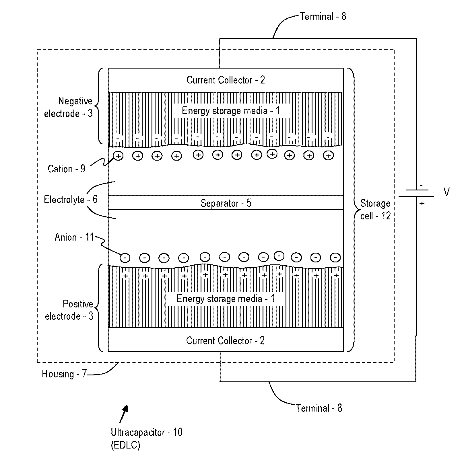
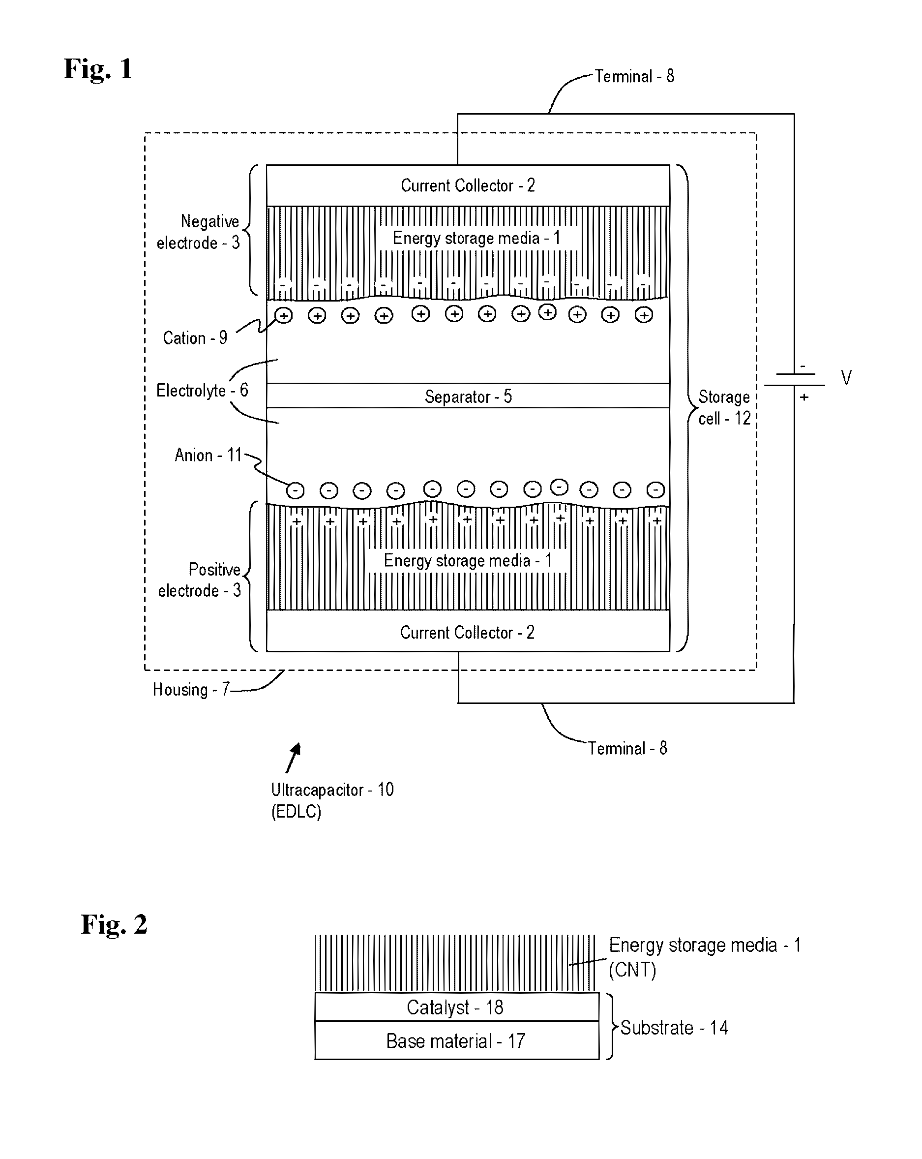
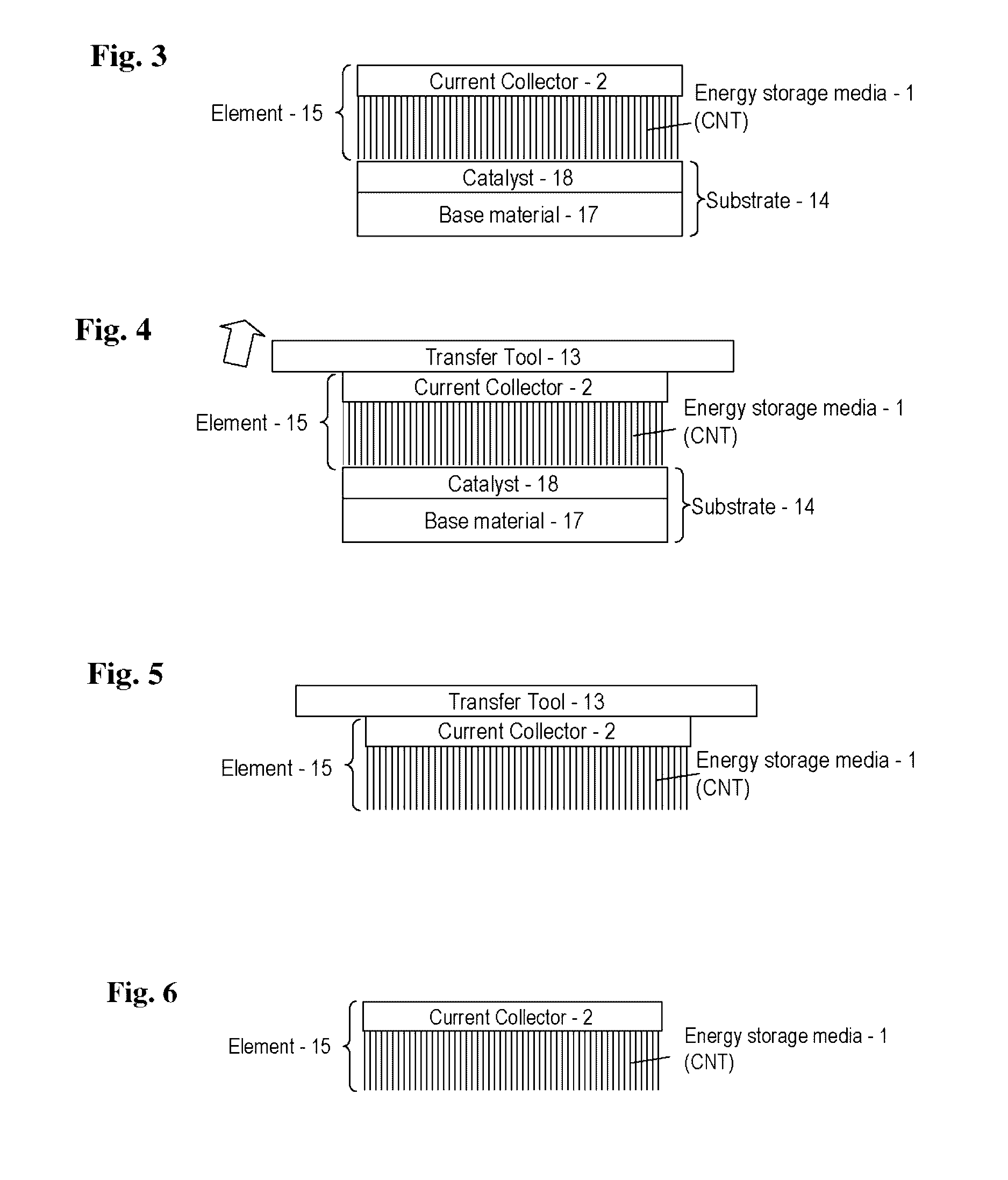

Image

  • Advanced electrolyte systems and their use in energy storage devices
  • Advanced electrolyte systems and their use in energy storage devices
  • Advanced electrolyte systems and their use in energy storage devices

Examples


Embodiment Construction

[0060]In the present application a variety of variables are described, including but not limited to components (e.g. electrode materials, electrolytes, etc.), conditions (e.g., temperature, freedom from various impurities at various levels), and performance characteristics (e.g., post-cycling capacity as compared with initial capacity, low leakage current, etc.). It is to be understood that any combination of any of these variables can define an embodiment of the invention. For example, a combination of a particular electrode material, with a particular electrolyte, under a particular temperature range and with impurity less than a particular amount, operating with post-cycling capacity and leakage current of particular values, where those variables are included as possibilities but the specific combination might not be expressly stated, is an embodiment of the invention. Other combinations of articles, components, conditions, and / or methods can also be specifically selected from am...


PUM

PropertyMeasurementUnit
operational temperatureaaaaaaaaaa

Abstract

An ultracapacitor that includes an energy storage cell immersed in an advanced electrolyte system and disposed within a hermetically sealed housing, the cell electrically coupled to a positive contact and a negative contact, wherein the ultracapacitor is configured to output electrical energy within a temperature range between about −40 degrees Celsius to about 210 degrees Celsius. Methods of fabrication and use are provided.

Description

CROSS REFERENCE TO RELATED APPLICATIONS[0001]This application claims the benefit of priority under 35 U.S.C. §119(e) to U.S. Provisional Patent Application Ser. No. 61 / 602,713, filed Feb. 24, 2012, entitled “Electrolytes for Ultracapacitors” and U.S. Provisional Patent Application Ser. No. 61 / 724,775, filed Nov. 9, 2012, entitled “Electrolytes for Ultracapacitors”. This application is also a continuation-in-part of International Patent Application Serial No. PCT / US2012 / 045994, filed, Jul. 9, 2012, entitled “High Temperature Energy Storage Device,” which claims priority under 35 U.S.C. §119(e) to U.S. Provisional Application Ser. No. 61 / 505,715, filed on Jul. 8, 2011, entitled “BARRIER FOR A CAPACITOR”; U.S. Provisional Application Ser. No. 61 / 512,090, filed on Jul. 27, 2011, entitled “ALUMINUM HOUSING WITH A HERMETIC SEAL”; U.S. Provisional Application Ser. No. 61 / 560,888, filed on Nov. 17, 2011, entitled “HEMISPHERIC HERMETIC SEAL”; U.S. Provisional Application Ser. No. 61 / 569,010,...

Claims


Application Information

Patent Timeline
Patent Type & Authority Patents(United States)
IPC IPC(8): H02J7/00H01G11/30H01G11/34H01M10/0568H01M10/052H01G11/52H01G11/36H01M2/06H01M2/16H01M10/0563H01M50/423H01M50/426H01M50/437H01M50/491
CPCH01G11/30H01G11/34H01G11/36H01G11/52H01M10/052H01M10/0568H02J7/00H01M2/065H01M2/1613H01M2/1646H01M2/1653H01M10/0563Y02E60/122Y02P70/54Y02E60/13Y02E60/10H01M50/186H01M50/191H01M50/44H01M50/437H01M50/491H01M50/423H01M50/426Y02P70/50
Inventor SIGNORELLI, RICCARDOCOOLEY, JOHN J.DEANE, CHRISTOPHER JOHN SIBBALDEPSTEIN, JAMESKUTTIPILLAI, PADMANABAN SASTHANMARTINI, FABRIZIOWILHELMUS, LINDSAY A.
Owner FASTCAP SYST
Learn More