Handheld robot for orthopedic surgery and control method thereof

a hand-held robot and orthopedic surgery technology, applied in the field of surgical robots, can solve the problems of compromising the precision of the result, complicating the positioning process, and errors in positioning, so as to achieve the effect of enhancing the precision of the orthopedic surgery and minimizing the errors of the surgery

Active Publication Date: 2017-02-07
NAT TAIWAN UNIV +1
View PDF20 Cites 181 Cited by
  • Summary
  • Abstract
  • Description
  • Claims
  • Application Information

AI Technical Summary

Benefits of technology

[0009]Based on the above reasons, a primary objective of the present invention is to provide a handheld robot for orthopedic surgeries. The handheld robot provided by the present invention is able to combine the relative position / orientation information between a tool and a bone acquired by a positioning unit with the force / torque information feedback by the bone acquired by a force sensor, and is able to utilize the combined information to compensate the motion of the handheld robot in a quick and timely manner, so as to keep the tool within the range / path of a predetermined operation plan. As a result, the precision of the orthopedic surgery can be enhanced, and the error occurred during the surgery can be minimized.
[0010]Another objective of the present invention is to provide a tool specifically designed for further detecting a deviation force between the bone and the tool. With the design of the present invention, the sensitivity of the motion compensation of the tool is improved, thereby preventing the tool from deviating from the path of the predetermined operation plan.

Problems solved by technology

In a surgery where surgical jigs are used to help with the measuring and the positioning of the cut, surgeons often need to switch surgical jigs during one operation multiple times, which can lead to errors in the positioning.
However, in the actual surgeries, surgeons need to constantly adjust the cutting block manually to position / orientate the cutting block as instructed by the navigation program, which complicates the positioning process.
However, in the process of mounting the cutting block with the adjusting screw, the precision of the result might still be compromised due to the error occurred during the process of fixing the adjusting screw.
However, due to the response bandwidth of the optical positioning system, the reaction speed of the robotic arm is limited, which compromises the precision of the operation.
In addition, blockage is a more serious matter which occurs quite often in the optical positioning system.
When the light-reflecting balls are blocked by obstacles, the optical positioning system cannot provide the relative position and orientation between the bones and the robotic arm.
Hence, in the situation where only optical positioning system is used to assist with the motion compensation of the robotic arm, the position of the robotic arm cannot be adjusted in time, which can endanger the safety of the patient.
Furthermore, compared with the conventional bone cutting tool, the size of the robotic arm is way too huge, which causes inconveniences for the surgeons, and also limits the application thereof.
Such control methods lack the ability to keep the front end of the tool within the range / path of the operation plan; therefore, surgeons need to control the movement of the robotic arm manually through out the whole operation process, which can be very exhausting.

Method used


Image

  • Handheld robot for orthopedic surgery and control method thereof
  • Handheld robot for orthopedic surgery and control method thereof
  • Handheld robot for orthopedic surgery and control method thereof

Examples


Embodiment Construction

[0039]The accompanying drawings are included to provide a further understanding of the invention, and are incorporated in and constitute a part of this specification. The drawings illustrate embodiments of the invention and, together with the description, serve to explain the principles of the invention.

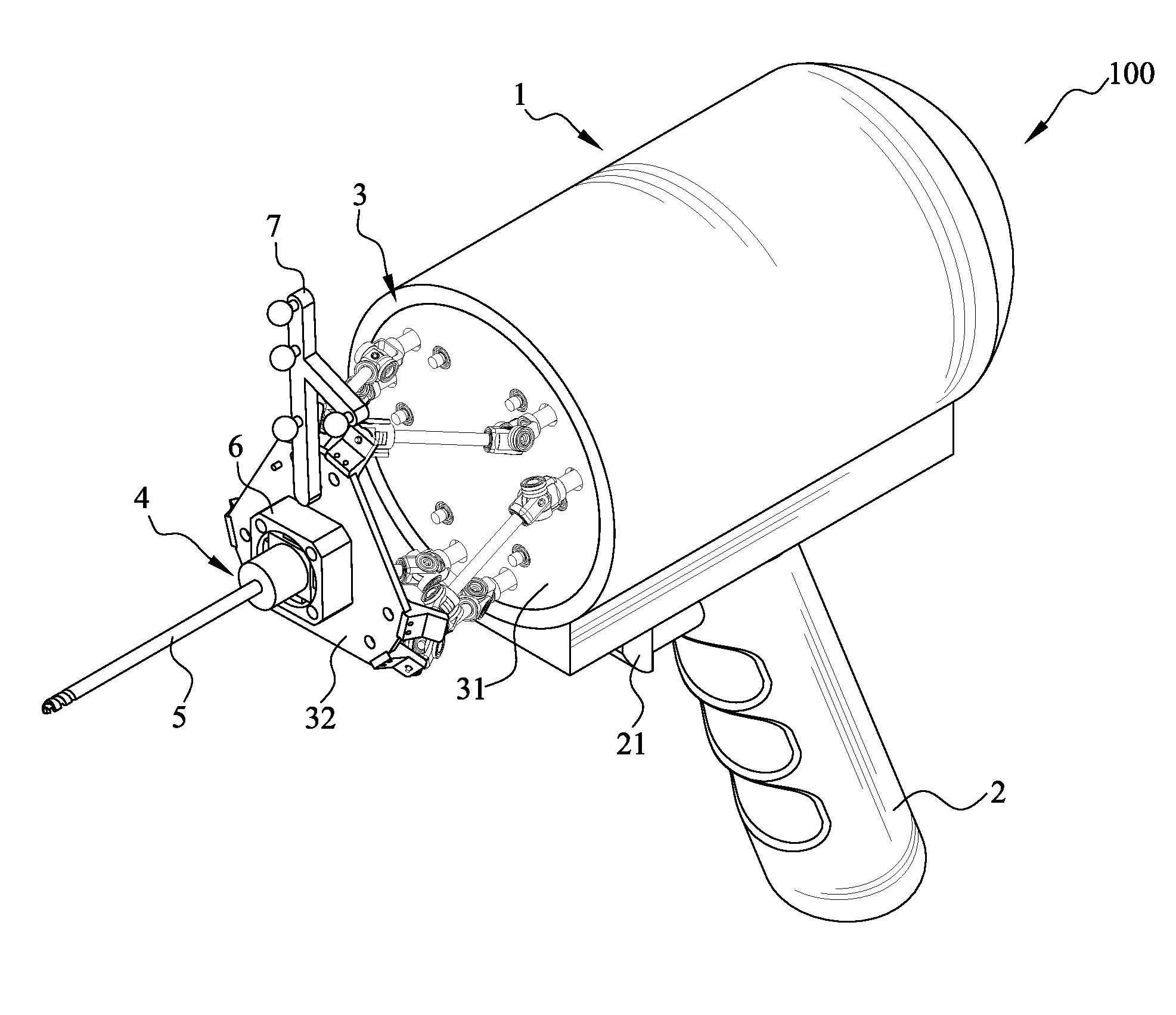
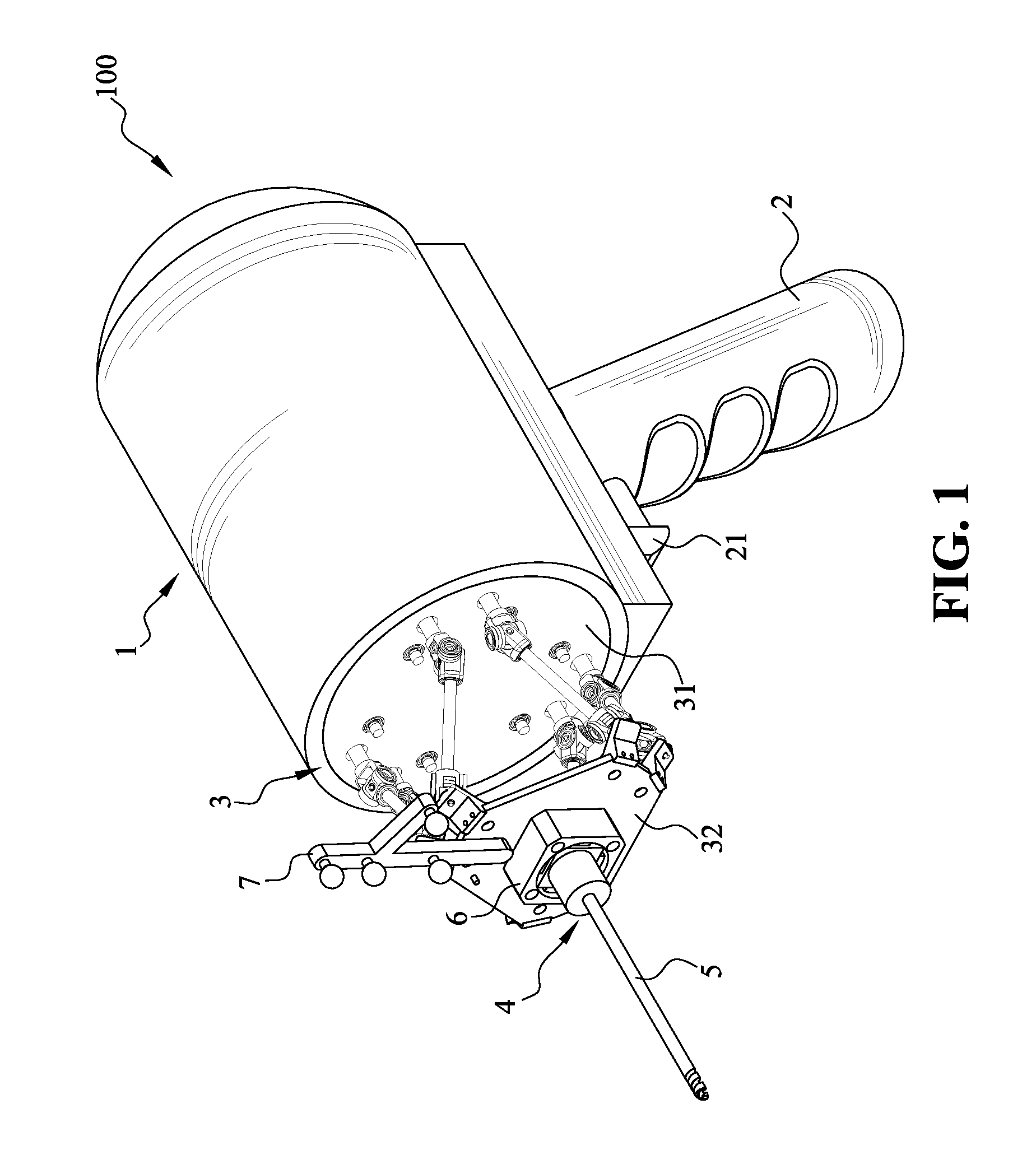
[0040]FIG. 1 is a perspective view showing a handheld robot 100 for orthopedic surgery of the present invention. As shown in FIG. 1, the handheld robot 100 according to a preferred embodiment of the present invention 100 includes: a main body 1, a grip 2, a kinematic mechanism 3, a tool connector, a tool 5, a force sensor and a positioning unit 7.

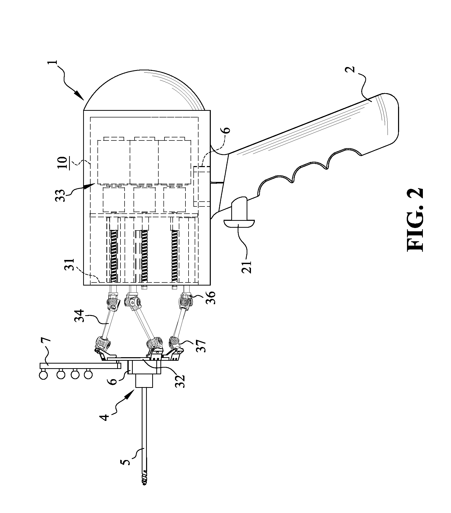
[0041]FIG. 2 is a side view showing the handheld robot 100 according to the preferred embodiment of the present invention, and FIG. 3 is an exploded and perspective view of the handheld robot 100 according to the preferred embodiment of the present invention. As shown in FIG. 1˜FIG. 3, the main body 1 has an inner space 10, and the grip 2 is...


PUM


Abstract

The present invention provides a handheld robot for orthopedic surgery and a control method thereof. The handheld robot of the present invention includes a main body, a grip, a kinematic mechanism, a tool connector, a tool, a force sensor and a positioning unit. The handheld robot of the present invention combines the position / orientation information of the tool acquired by the positioning unit with the force / torque information acquired by the force sensor, and utilizes the combined information to adjust the position of the tool so as to keep the tool within the range / path of a predetermined operation plan. In this way, the precision of the orthopedic surgery can be enhanced, and the error occurred during the surgery can be minimized.

Description

CROSS-REFERENCES TO RELATED APPLICATIONS[0001]This application claims the priority of Taiwanese patent application No. 102149096, filed on Dec. 30, 2013, which is incorporated herewith by reference.BACKGROUND OF THE INVENTION[0002]1. Field of the Invention[0003]The present invention relates generally to a surgical robot, and more particularly, to a handheld robot for orthopedic surgery and the control method thereof. The handheld robot of the present invention is able to combine the position / orientation information of a tool acquired by a positioning unit with the force / torque information acquired by a force sensor, and is able to utilize the combined information to compensate the motion of the handheld robot.[0004]2. The Prior Arts[0005]In the field of orthopedic surgery, surgical jigs, computer aided navigation program or image-guided robotic arm are commonly used to assist surgeons to position the bones during the operation, such as an osteotomy, or surgeries that requires the su...

Claims


Application Information

Patent Timeline
Patent Type & Authority Patents(United States)
IPC IPC(8): A61B17/16A61B17/88A61B17/17G05B15/02A61B17/15
CPCA61B34/76A61B17/16A61B17/1622A61B17/1626A61B17/1703A61B17/8875A61B34/20A61B34/30A61B34/75G05B15/02A61B17/155A61B2034/2055A61B2034/304A61B2090/061A61B2090/064A61B2090/066A61B2090/08021B25J1/00B25J9/1005B25J9/1623B25J15/0019B25J17/0216
Inventor YEN, PING-LANGHUNG, SHUO-SUEI
Owner NAT TAIWAN UNIV
Why Eureka
Try Eureka