Linear composite transmitter utilizing composite power amplification

a technology of composite power amplifier and linear amplifier, which is applied in the direction of high frequency amplifier, secret communication, baseband system details, etc., can solve the problems of limiting the ability to achieve both a good power efficiency and a good psd characteristic over a wide frequency bandwidth, and achieve the effect of improving power efficiency

Active Publication Date: 2017-02-07
FODAN
View PDF43 Cites 10 Cited by
  • Summary
  • Abstract
  • Description
  • Claims
  • Application Information

AI Technical Summary

Benefits of technology

[0100]It is noted that the composite transmitter 201 differentiates the frequencies of a main signal and an efficiency improving signal (EIS) and that the power combiner 40 is structured in a symmetrical configuration to combine the powers of the two power amplifiers 50 and 51, so that output impedances of the main signal and the efficiency improving signal can be set up independently. As a result, the composite transmitter 201 enables operations of the two power amplifiers 50 and 51 with nearly the maximum power efficiency over a wide range of frequency and a wide range of input signal level, in contrast to the Chireix transmitters 101 and the Doherty transmitters 103 which can maximize their power efficiencies only at center frequencies and limited levels for a given input signal.

Problems solved by technology

Since the structure of a power combiner for combining two outputs of two power amplifiers is relatively complex, there has been a limit to achieve both a good power efficiency and a good PSD characteristic over a wide frequency bandwidth.

Method used


Image

  • Linear composite transmitter utilizing composite power amplification
  • Linear composite transmitter utilizing composite power amplification
  • Linear composite transmitter utilizing composite power amplification

Examples


embodiment 1

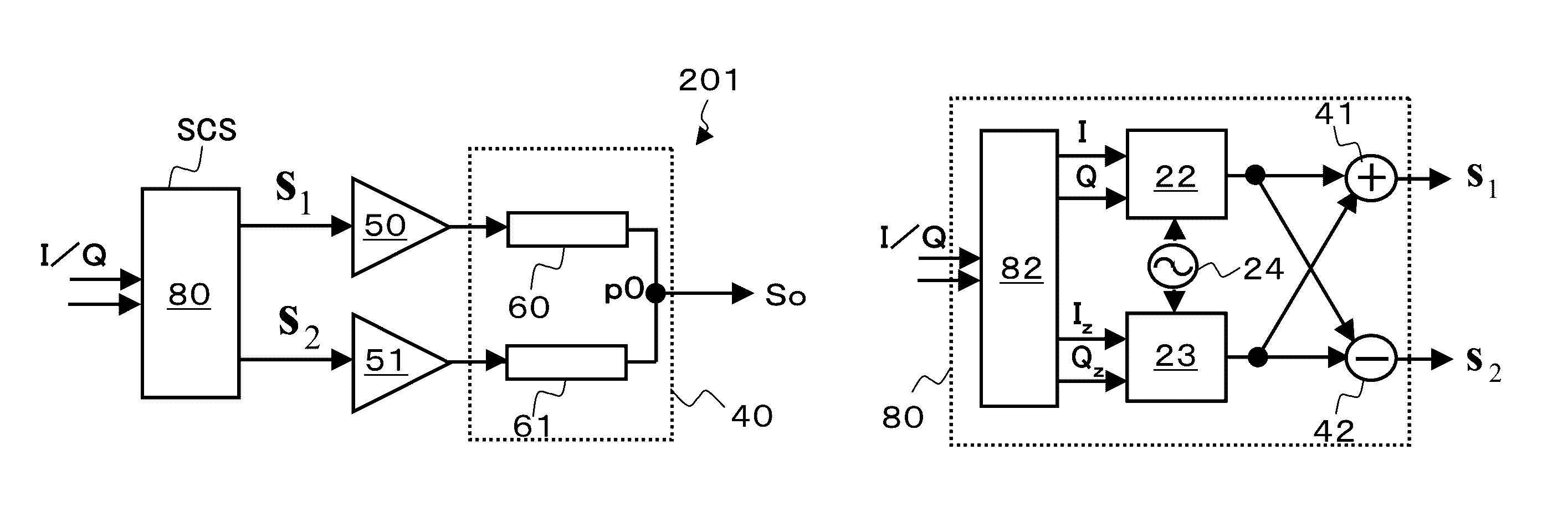
[0135]Referring to FIG. 10, there is shown a composite transmitter 201 according to the invention, which comprises the following three components.

[0136](1) A signal component separating device 80 which, upon receipt of an in-phase baseband signal I(t) and an orthogonal baseband signal Q(t), outputs[0137]a first composite signal S1(t) in the form of a vectorial sum of[0138]a main signal A(t) obtained by orthogonal modulation of the in-phase signal I and the orthogonal signal Q and[0139]an efficiency improving signal (EIS) obtained from the main signal by subjecting the main signal to frequency shifting and envelope conversion, and[0140]a second composite signal S2(t) in the form of a vectorial difference between the main signal and the EIS;

[0141](2) A first power amplifier 50 for power amplifying the first composite signal S1(t) and a second power amplifier 51 for power amplifying the second composite signal S2(t); and

[0142](3) A power combiner 40 having a symmetric structure for com...

embodiment 2

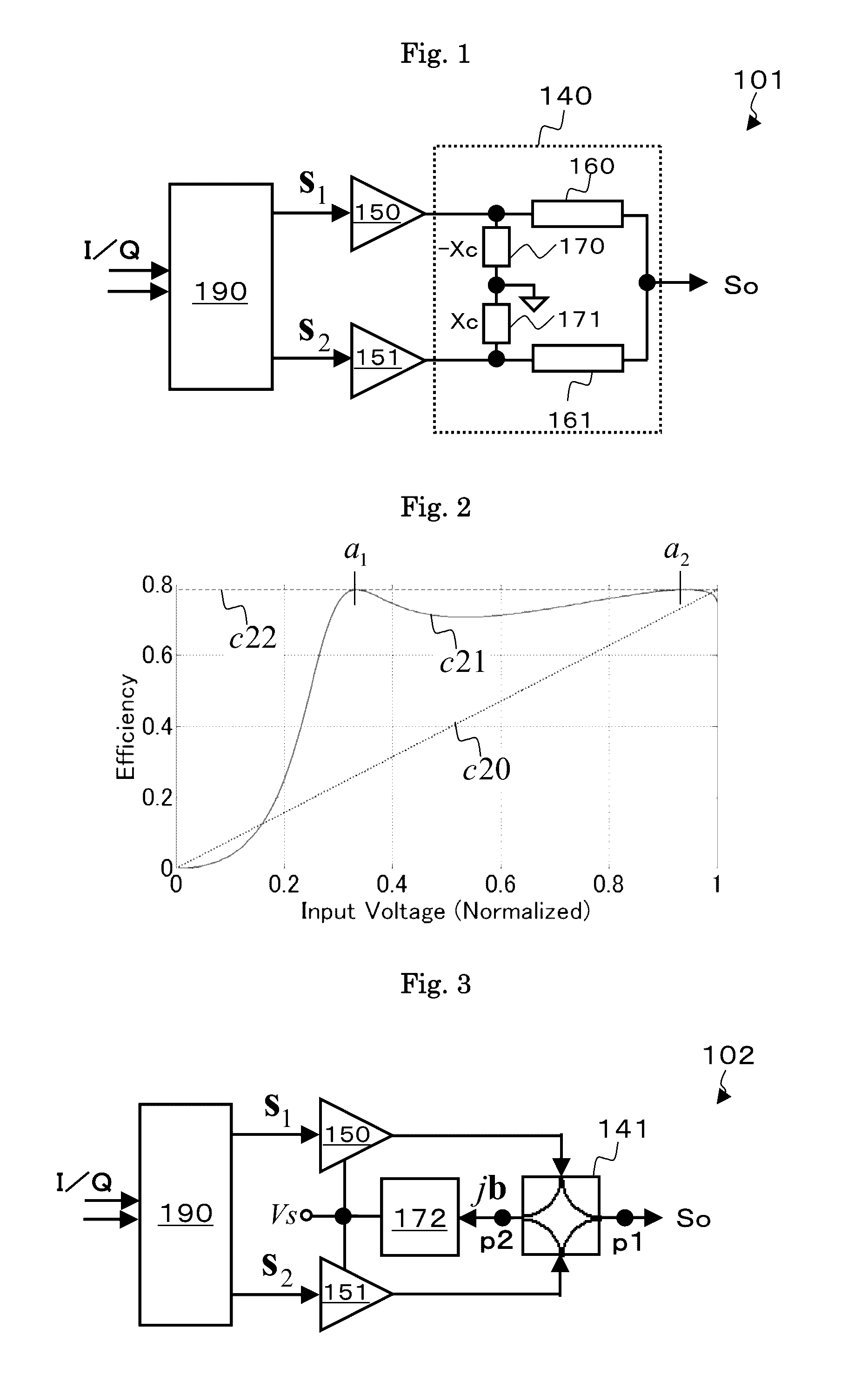
[0153]The composite transmitter 202 (not shown) is a modified version of a conventional Chireix transmitter (FIG. 3), modified in such a way that, the signal component separating device provides:

[0154]a phase determination signal u(t) (simply referred to as u) which equals +1 if the main signal has a phase in the range between θ0−π / 2 and θ0+π / 2 but equals −1 otherwise, where θ0 is an arbitrarily set phase, and provides an EIS (Eq. 4), whose vectorial form is given by the following equation

jb=jb(t)exp{φ(t)}  (Eq. 18)

where b(t)=√{square root over (C2−a(t)2)}, and C is the peak envelope level of the main signal.

[0155]A first and a second vectorial composite signals S1 and S2, respectively, given by Eqs. 19 and 20, respectively.

S1=a+jub  (Eq. 19)

S2=a−jub(Eq. 20)

[0156]Denoting the main signal by I+jQ and the EIS by Iz+jQz, and defining the quantity b(t) / a(t), or √{square root over (C2 / a(t)2−1)} as envelope conversion signal, the in-phase signal Iz of the EIS turns out to be a product of ...

embodiment 3

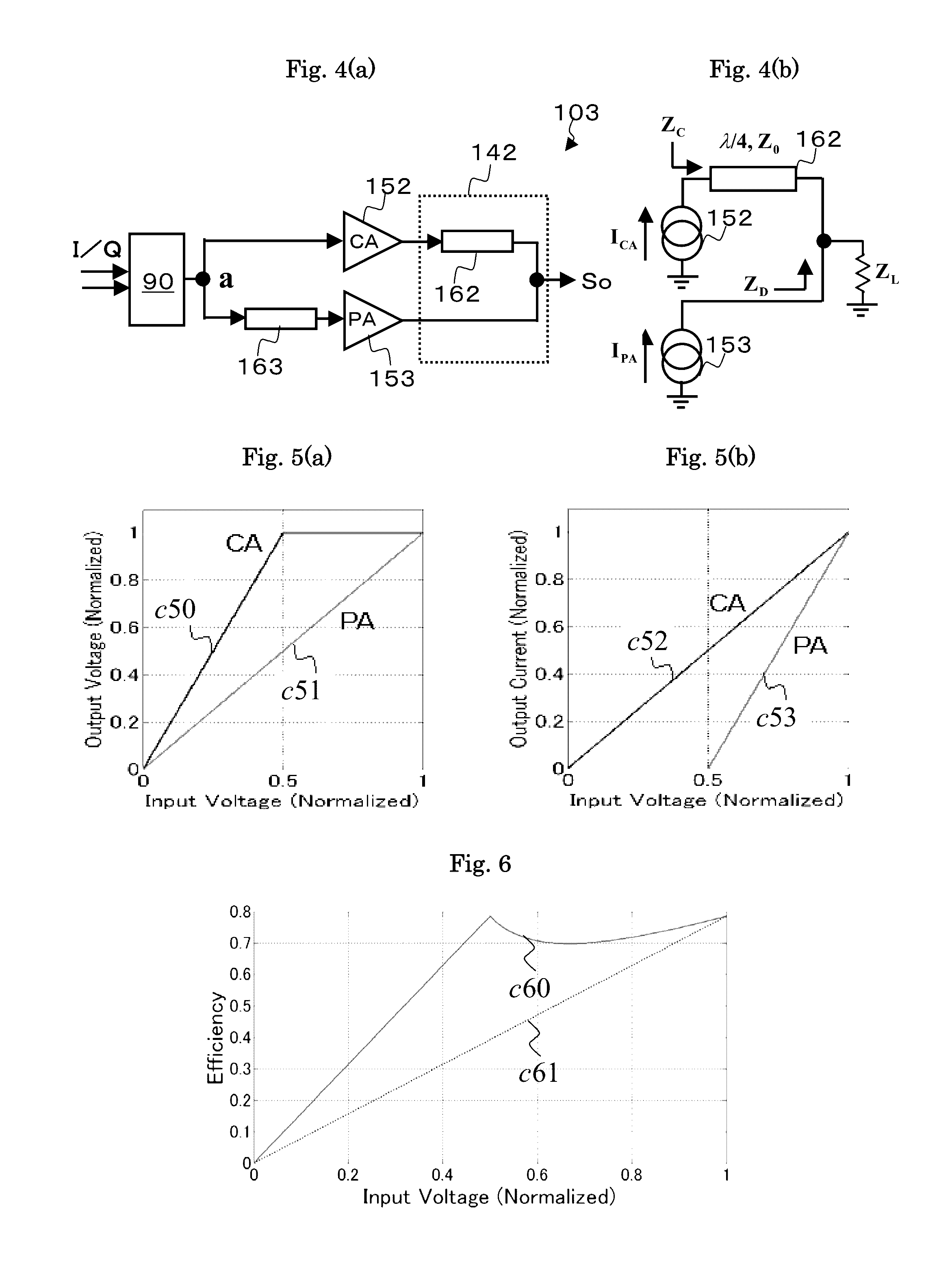
[0164]The inventive composite transmitter 203 (not shown) is a modification of the Doherty transmitter 104 obtained by replacing the Doherty's power combiner 142 with a structurally symmetric power combiner 40. With the EIS vector a1 given by Eq. 22,

[0165]a⁢⁢1=⁢a⁢(0≤a⁡(t)≤C / 2)=⁢{C / a-1}⁢a⁢(C / 2≤a⁡(t)≤C)(Eq.⁢22)

The first composite signal S1 which is a vectorial sum of the main signal, the phase determination signal u, and the EIS and the second composite signal S2 which is a vectorial difference between the main signal and the EIS are given by the following Eqs. 23 and 24, respectively.

S1=a+ua1  (Eq. 23)

S2=a−ua1  (Eq. 24)

[0166]In order to narrow the frequency bandwidth of the EIS of the composite transmitter 203, it is also important for an improvement of its ACLR characteristic to reduce the spectral regrowth power density. FIG. 15 shows behaviors of the main signal A, the EIS ua1 the first composite signal S1, and the second composite signal S2 on the phase plane referenced to the ca...


PUM


Abstract

The present invention provides a compound transmitter having power efficiency characteristics and distortion characteristics superior, over a wide band, to those of a Doherty transmitter, and having fewer elements constituting an RF circuit. The present invention is therefore provided with a compound amplifier (201) for generating a signal (z) (efficiency improving signal) obtained by the amplitude modulation of a carrier signal from an RF modulation signal (a) (main signal); power-modulating, using two power amplifiers (50, 51), a signal (S1) obtained by adding together (a) and (z), and a signal (S2) obtained by subtracting (z) from (a); and setting, as a transmitter output point, the point (p1) where the respective outputs are combined via impedance inverters (60, 61), the efficiency improving signal (z) being generated under conditions in which the size of the envelope of either (S1) or (S2) is fixed.

Description

FIELD OF THE INVENTION[0001]This invention relates to a power amplifier and a transmitter for use in a base station and with terminals of a mobile wireless communication system (e.g. micro-wave mobile phones), a satellite communication system, and a broadcasting system.[0002]More particularly, the invention relates to a composite power amplifier for linear amplification of an RF modulated signal, e.g. a multi-carrier signal having a large peak envelope power as compared with its average output power. The inventive composite transmitter is simpler in structure than conventional ones, yet it has an improved linearity and power efficiency characteristics.BACKGROUND ART[0003]The present invention pertains to an improvement of a composite power amplifier such as a Chireix power amplifier (See Non-patent Document 1) and a Doherty power amplifier (Non-patent document 2), the improvement directed to remove a disadvantageous narrow band characteristic of such composite power amplifier. The C...

Claims


Application Information

Patent Timeline
Patent Type & Authority Patents(United States)
IPC IPC(8): H04K1/02H04L25/03H04L25/49H04B1/04H03F1/02H03F3/189H03F3/24H03F3/19H03F3/21
CPCH04B1/0475H03F1/0288H03F1/0294H03F3/189H03F3/19H03F3/211H03F3/245H03F2200/102H03F2200/204H03F2200/207H03F2200/336H03F2200/451H03F2203/21106H03F2203/21142H04B2001/045H03F1/02H03F3/24
Inventor KURIHARA, HIROSHI
Owner FODAN
Why Eureka
Try Eureka