
System and method for controlling autonomous or semi-autonomous vehicle

Active Publication Date: 2017-02-14
MITSUBISHI ELECTRIC RES LAB INC
View PDF9 Cites 157 Cited by
  • Summary
  • Abstract
  • Description
  • Claims
  • Application Information

AI Technical Summary

Benefits of technology

This patent describes a method and system for controlling the motion of an autonomous vehicle. The system uses a model of the vehicle's motion and obstacles in its environment to determine the best way to move the vehicle based on the control inputs. The controller then maps these controls to the vehicle's systems and controls its motion accordingly. This approach allows for smoother and safer driving, by considering the vehicle's current state and making appropriate changes to its motion based on the control inputs. Overall, this technology makes it easier to control the autonomous vehicle's motion and reduces the risk of collisions with obstacles.

Problems solved by technology

However, the sensor information is noisy and uncertain, the exact parameters of the vehicle are unknown, and the environment is only partially known.
The location and velocity of the obstacles are uncertain, due to sensing noise and other sources of uncertainty.
When only considering predictions of future paths, the computational complexity of the method is reduced, but it can result in a nondrivable path.
The result is either that the quality of the motions cannot be guaranteed in real-time operation, or that the motion the autonomous vehicle should follow is not determined sufficiently fast, or a combination of the both.
A cause of the lack of quality of motion in combination with computational / memory load is that the quality of the motion is determined by investigating the entire motion, from initial state to target state.
Therefore, the tree of possible motions becomes unnecessarily large.
In such a case, the computational / memory load can be overwhelming.

Method used


Image

  • System and method for controlling autonomous or semi-autonomous vehicle
  • System and method for controlling autonomous or semi-autonomous vehicle
  • System and method for controlling autonomous or semi-autonomous vehicle

Examples


Embodiment Construction

[0038]Some embodiments of the invention are based on the realization that the quality of the motion of the vehicle can be achieved by evaluating the quality of the control input taking the vehicle from one state to another state, instead of evaluating the entire motion from the current state to target state. As used herein, the state of the vehicle includes dynamics of the vehicle, such as locations, velocities, and headings of the vehicles.

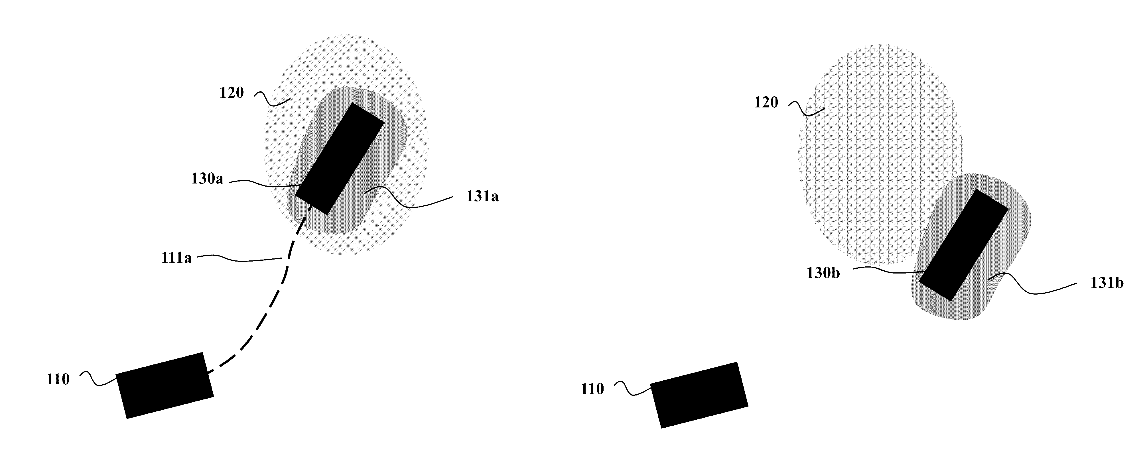
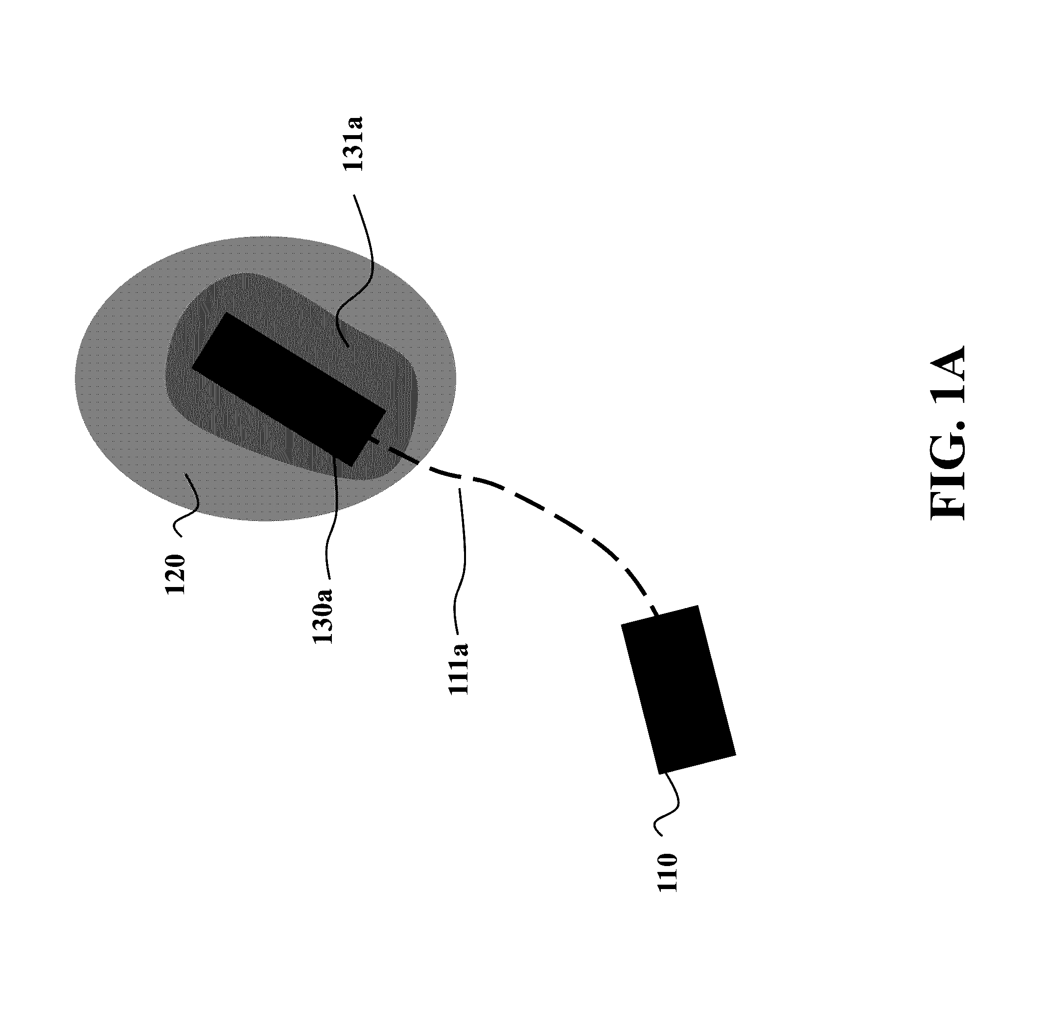
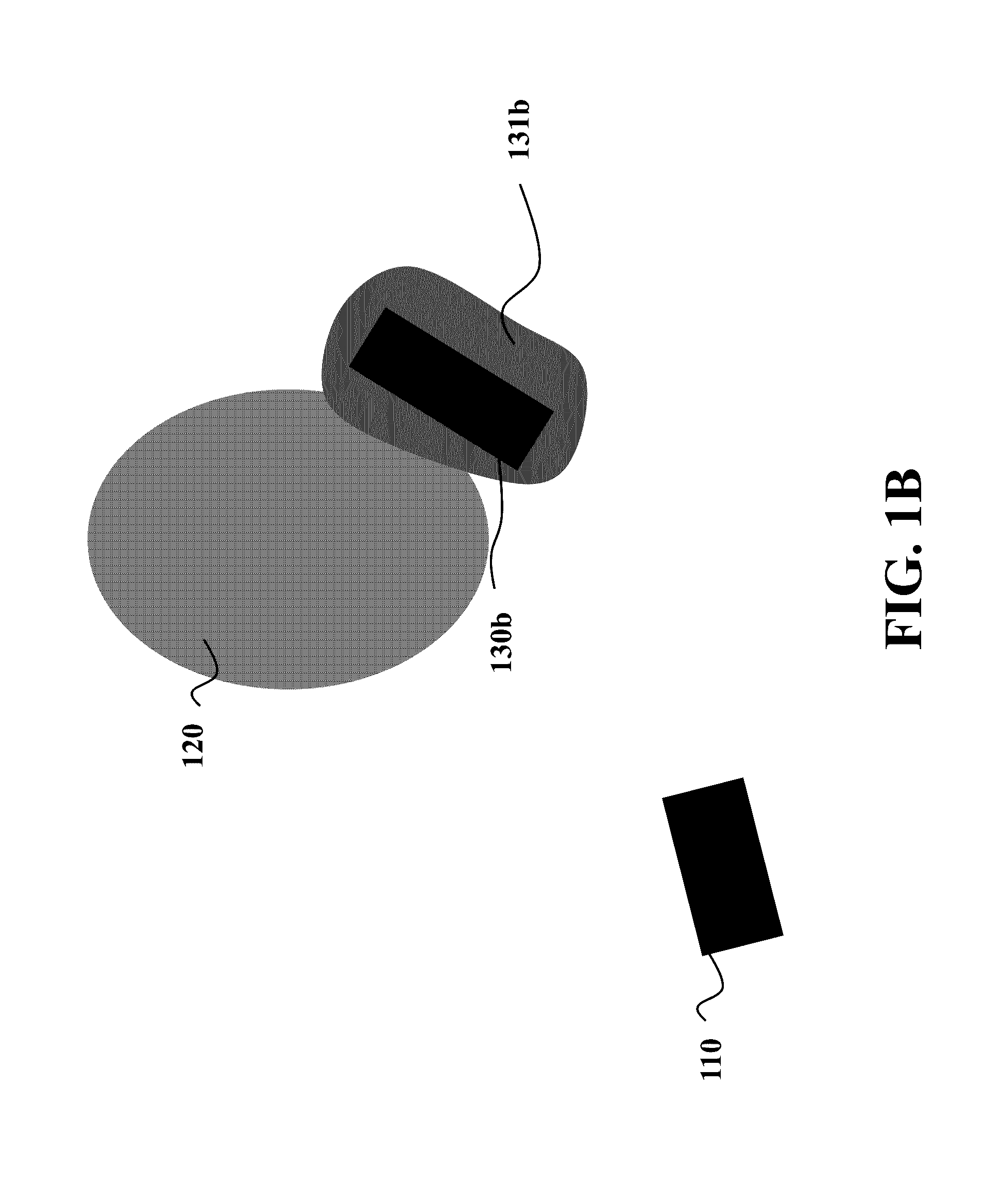
[0039]FIG. 1A shows an example of an initial state of an autonomous vehicle 110 and a next state 120. The next state 120 can be a Cartesian position, a velocity, or another entity associated with the vehicle. The next state 120 can be a specific state, or a region of states. For example, the next state 120 can be an interval of allowed velocities or a region of possible locations in Cartesian space. A suitable control input is an input that takes the vehicle 110 from its initial state to next state 120. The resulting state 130a from an input can ...


PUM


Abstract

A method controls a motion of a vehicle using a model of the motion of the vehicle that includes an uncertainty. The method samples a control space of possible control inputs to the model of the motion of the vehicle to produce a set of sampled control inputs and determines a probability of each sampled control input to move the vehicle into state satisfying constraints on the motion of the vehicle. The method determines, using the probabilities of the sampled control inputs, a control input having the probability to move the vehicle in the state above a threshold. The control input is mapped to a control command to at least one actuator of the vehicle to control the motion of the vehicle.

Description

FIELD OF THE INVENTION[0001]The present invention relates generally to controlling vehicles, and more particularly to controlling an autonomous or a semi-autonomous vehicle.BACKGROUND OF THE INVENTION[0002]Several control systems employed by vehicles, either autonomous vehicles or vehicles executing in autonomous-driving mode, predict future, safe motions of the vehicle toward some target state, both in order to avoid obstacles, such as other vehicles or pedestrians, but also to optimize some criteria associated to the operation of the vehicle. The target state can either be a fixed location, a moving location, a velocity vector, a region, or a combination thereof. The surroundings, such as road edges, pedestrians, and other vehicles, are sensed by the sensors of the vehicle and / or are at least partially known by a priori given information. However, the sensor information is noisy and uncertain, the exact parameters of the vehicle are unknown, and the environment is only partially k...

Claims


Application Information

Patent Timeline
IPC IPC(8): G01C22/00G05D1/00
CPCG05D1/0088G05D1/0214G06N3/006G06N20/00G06N5/01G06N7/01B60W30/095B60W30/00B60W50/0097
Inventor BERNTORP, KARLDI CAIRANO, STEFANO
Owner MITSUBISHI ELECTRIC RES LAB INC
Learn More