Parachute assembly for deploying a wireless mesh network

a wireless mesh network and parachute technology, applied in the field of adhoc communication networks, can solve the problems of parachuting, cost effectiveness of solution, light weight of parachute assemblies, etc., and achieve the effects of simple and cheap design, quick and easy establishment, and low cost of parachute assemblies

Active Publication Date: 2017-02-14
NAGRAVISION SA
View PDF24 Cites 0 Cited by
  • Summary
  • Abstract
  • Description
  • Claims
  • Application Information

AI Technical Summary

Benefits of technology

[0009]Some of the embodiments discussed herein may overcome at least some of the problems remaining in the prior art when it is required to quickly and cheaply establish a wireless ad-hoc or mesh network covering a desired area. A plurality of low-cost, lightweight, robust, non-guided systems is proposed. The system may be described as being a parachute assembly. The parachute assembly comprises a parachute and a payload. The parachute comprises a parachute frame, a parachute covering or membrane and at least one antenna. The payload comprises electronic equipment for setting up the communications network and is preferably of light weight. By having non-guided parachutes, the weight and the cost of the assemblies may be kept to a minimum since the payload need not comprise guidance devices. This also allows for the parachutes and payloads to be of simple, robust design. The parachute assemblies may therefore be deployed in large enough quantities to establish an adequate mesh network over the desired area. There is no need to perform accurate guidance of each individual parachute assembly. It is sufficient to distribute the parachutes with their payloads over a general area in sufficient quantities to provide the required communications coverage. This contributes to the cost effectiveness of the solution and to the light weight of the parachute assemblies.
[0030]allowing the plurality of systems to detect neighbouring systems and to build communication channels between themselves, thereby forming the wireless mesh network with an entry point and an exit point.
[0032]Embodiments described herein may be used to cheaply, quickly and easily provide wireless communication in an area having no connectivity to an already established communications network and / or having very few inhabitants, thereby allowing for users in those areas to communicate electronically with each other or to connect to an already established Wide Area Network (WAN) such as the Internet. Similarly in areas where war has broken out or some disaster has occurred depriving that area of communications and power supply, embodiments of the present invention allow for a robust communications network to be established quickly, conveniently and cheaply without the need for the usual rather heavy infrastructure that would normally be required. A mesh network proposed by embodiments of the present invention, which could be deployed quickly and cheaply would solve many issues related to the provision of communications connectivity to a remote site.
[0033]The system used for the deployment of the mesh network does not need to be guided and therefore may use free-fall retarding devices which are very simple, cheap and light in design. As such, a simple parachute may be used as a free-fall retarding device to deploy small, light electronic circuitry, the parachute therefore having loose design constraints thereby allowing for a light metal structure to be used as a frame and for the frame to be used as an antenna for the electronic circuitry.

Problems solved by technology

The prior art teaches the use of free-fall retarding devices for deploying payloads but teaches away from the use of parachutes as free-fall retarding devices due to the non-predictability of their position during descent and upon landing and further due to the risk of damage to the payload during landing.
This contributes to the cost effectiveness of the solution and to the light weight of the parachute assemblies.

Method used


Image

  • Parachute assembly for deploying a wireless mesh network
  • Parachute assembly for deploying a wireless mesh network
  • Parachute assembly for deploying a wireless mesh network

Examples


Embodiment Construction

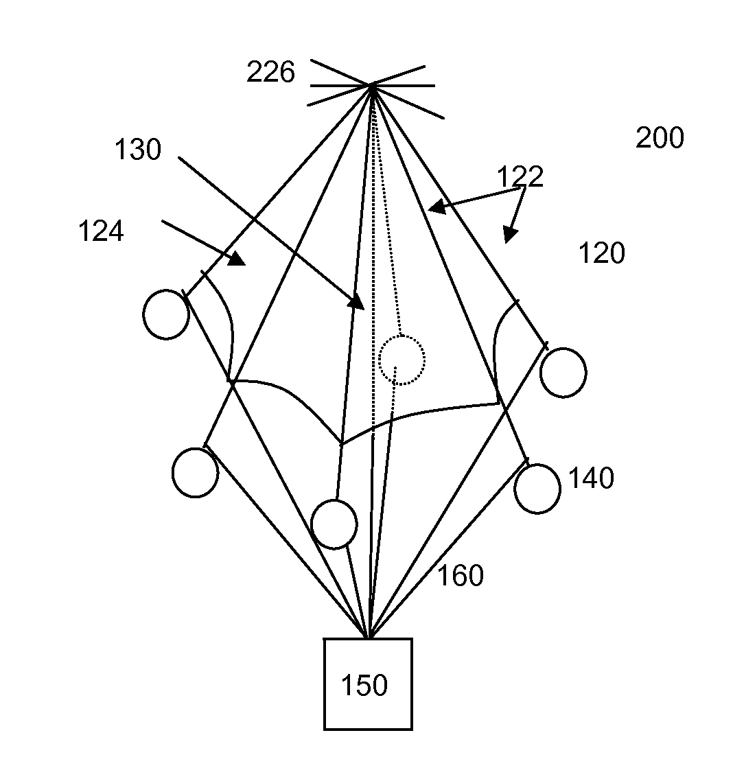
[0041]According to one embodiment, a plurality of small, low-cost and low-power electronic communications devices are used to establish a wireless mesh communications network. Examples of wireless communications presently in use are those operating according to the known standard 802.11, otherwise known as WiFi. For the purpose of the present invention, any wireless, RF (Radio Frequency) protocol can be used as long as it provides support for a mesh network to be established i.e. a plurality of nodes within the network should be operable as a receiver and as a transmitter of packets and should be capable of discovering neighbouring nodes and establishing an optimal route for outgoing packets via one or more neighbouring nodes.

[0042]Depending on the application, the network could be secured by an additional layer of encryption (for example hardware encryption for military application). Also depending on the application, transit from node to node within the network could be encrypted ...


PUM


Abstract

The present invention relates to the deployment of a plurality of wireless communication devices in order to provide a wireless mesh communications network. According to various embodiments, deployment of the communications devices is made by parachutes suitably adapted for the purpose.

Description

CROSS REFERENCE TO RELATED APPLICATIONS[0001]This application claims under U.S.C. Section 119 to European Patent Application No. 13172559, filed Jun. 18, 2013, the entire contents of which are hereby incorporated by reference herein.TECHNICAL FIELD[0002]The present invention relates to the domain of ad-hoc communication networks, otherwise known as mesh networks and more particularly to developments in apparatus used to realize such networks and to methods used for deploying such apparatus in the field.BACKGROUND ART[0003]Ad-hoc communications networks, otherwise known as mesh networks are known in the state of the art. A wireless mesh network is a communications network comprising a number of wireless receivers, known as nodes, organised in a mesh topology, wherein each of the receivers is also capable of wirelessly transmitting a received signal to one or more of the other nodes in the network. On the other hand, a standard cellular network requires a backbone network connecting c...

Claims


Application Information

Patent Timeline
Patent Type & Authority Patents(United States)
IPC IPC(8): H04W8/00B64D17/00H04W84/18H04W16/18
CPCH04W8/005H04W84/18H04W16/18B64D17/02
Inventor CONUS, JOEL
Owner NAGRAVISION SA
Why Eureka
Try Eureka