Method for producing cold-worked centrifugal cast composite tubular products

a technology of composite tubular products and centrifugal casting, which is applied in the direction of furnaces, heat treatment furnaces, heat treatment equipment, etc., can solve the problems of limiting the choice of tubular components capable of withstanding the environment, grain size and casting defects, and higher temperatures and pressures in deeper wells

Active Publication Date: 2017-02-21
ATI FLOWFORM PROD
View PDF34 Cites 8 Cited by
  • Summary
  • Abstract
  • Description
  • Claims
  • Application Information

AI Technical Summary

Problems solved by technology

However, as wells become deeper, the downhole conditions in the well may limit the choice of tubular components capable of withstanding these environment.
Typically, deeper wells contain higher temperatures and pressures and may have corrosive atmospheres, e.g., hydrogen sulfide, carbon dioxide, chlorides, associated hydrocarbons, and / or acidic environments.
However, the as-cast component typically includes large grain sizes and may contain casting defects, such as porosity and nonmetallic inclusions.
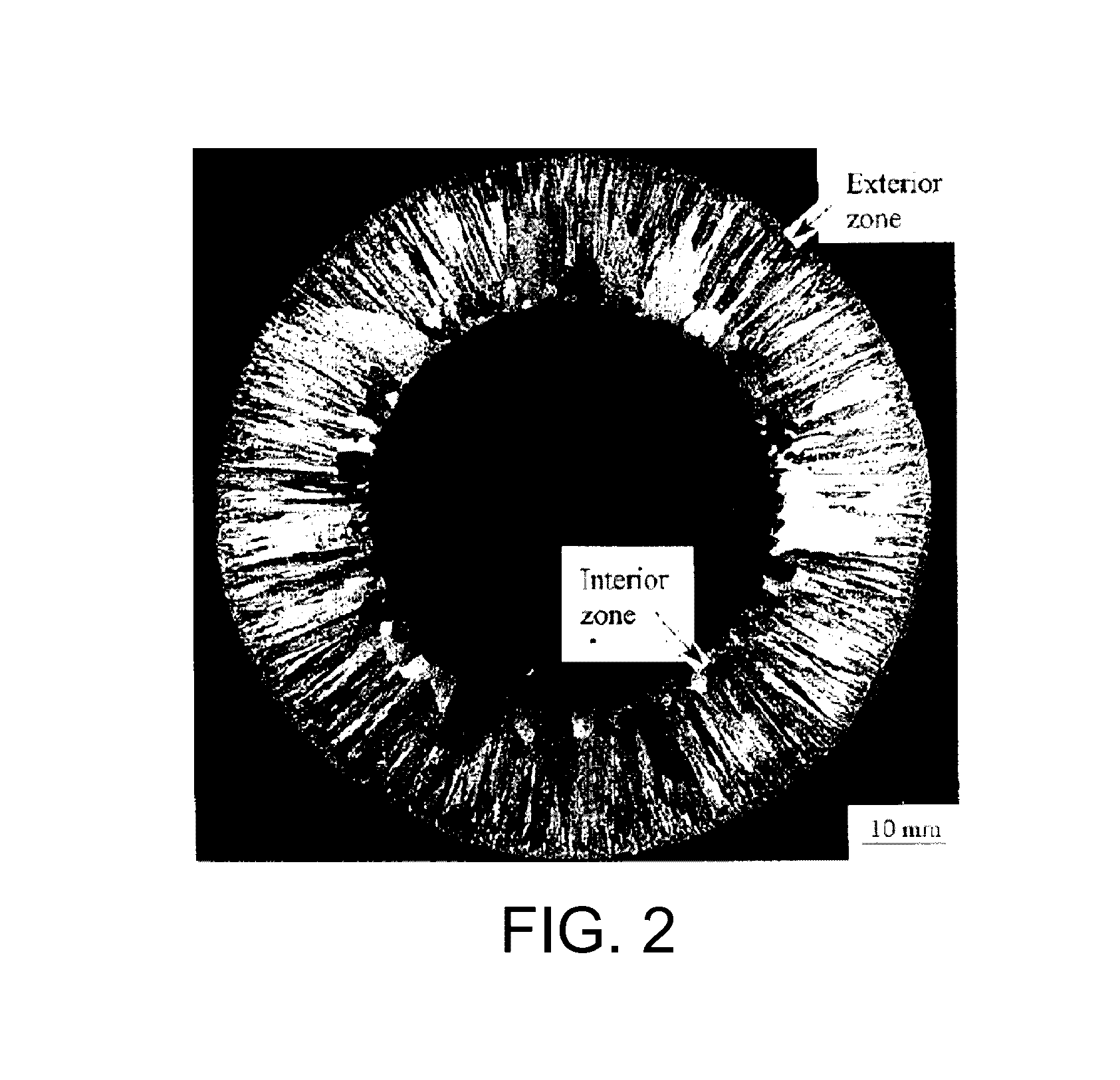
The resulting centrifugally cast component, however, presents many challenges for subsequent metal forming processes due to its different grain sizes in the various zones, along with its radially-oriented columnar grain structure.
However, warm and hot forming processes affect the mechanical properties and the dimensional accuracies of a component, making it difficult to meet requirements with tight tolerances.
In addition, centrifugal cast components have not been acceptable for applications with high internal pressure or where corrosive and / or erosive products are present, such as in environments where OCTG components are used.
The centrifugal casting process tends to produce a microstructure with undesirable porosity causing crack initiation sites.
One of the main problems of centrifugal cast components is the non-uniform microstructure through the cross section of the wall thickness.
The banded structure downgrades the physical and mechanical properties of the material and results in stratification.

Method used


Image

  • Method for producing cold-worked centrifugal cast composite tubular products
  • Method for producing cold-worked centrifugal cast composite tubular products
  • Method for producing cold-worked centrifugal cast composite tubular products

Examples


Embodiment Construction

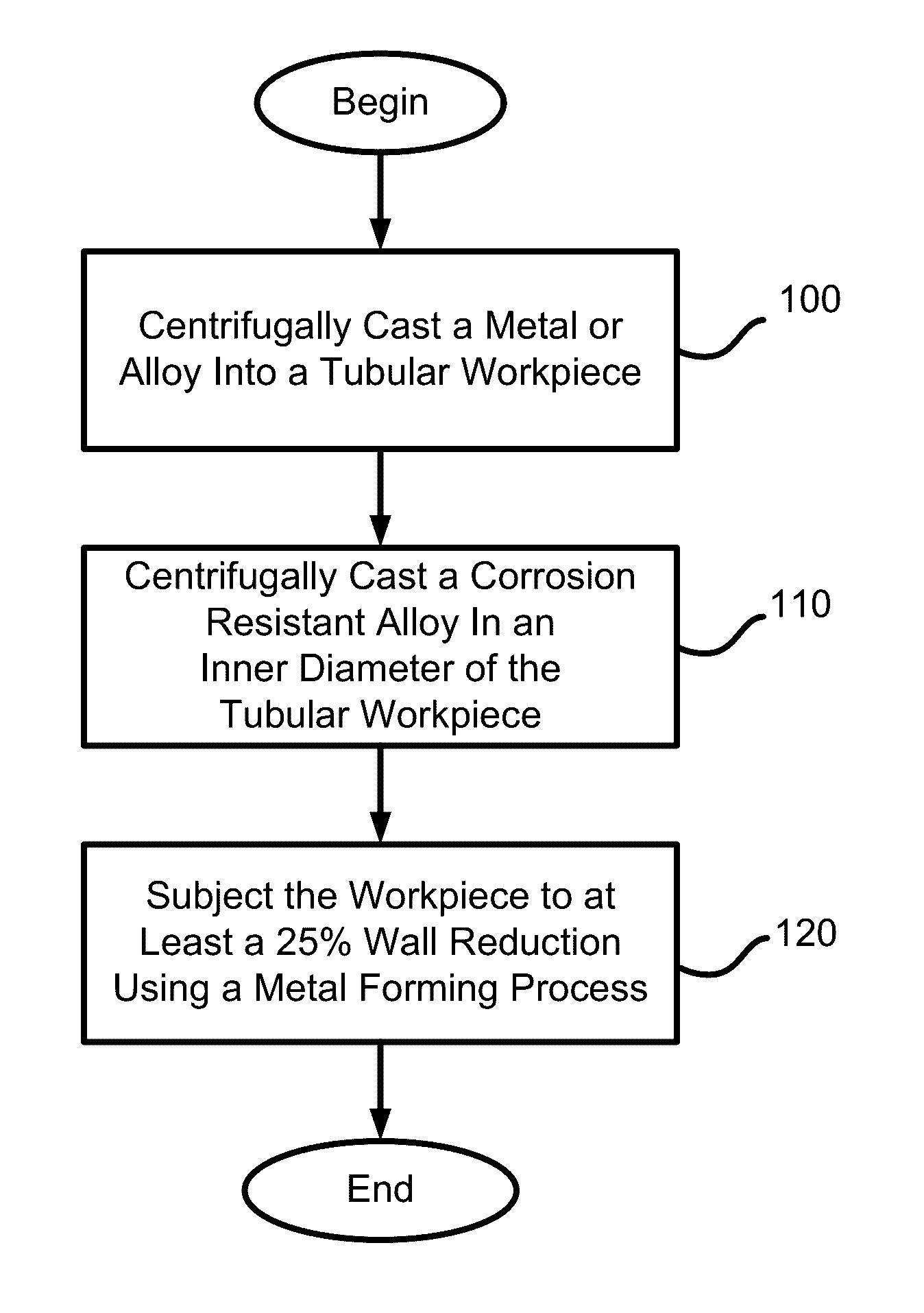
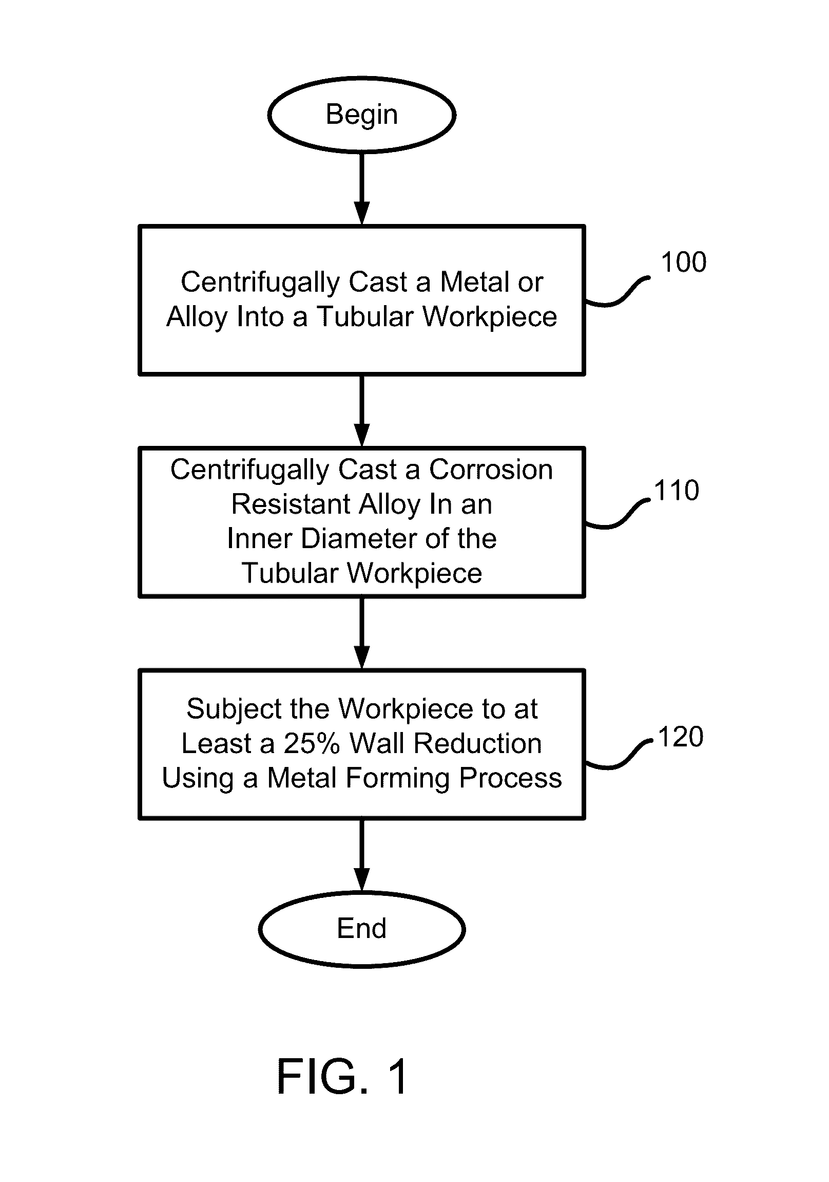
[0008]In accordance with one embodiment of the invention, a method of producing a seamless, composite tubular product includes centrifugally casting a metal or alloy into a tubular workpiece having an inner diameter. The method then centrifugally casts a corrosion resistant alloy in the inner diameter of the tubular workpiece to form a composite tubular workpiece having an inner diameter and an outer diameter, the inner diameter of the composite tubular workpiece formed of the corrosion resistant alloy and the outer diameter of the composite tubular workpiece formed of the metal or alloy. The method then subjects the composite tubular workpiece to at least about a 25% wall reduction at a temperature below a recrystallization temperature of the composite tubular workpiece using a metal forming process. The metal forming process includes radial forging, rolling, pilgering, and / or flowforming.

[0009]In some embodiments, the method further includes centrifugally casting one or more metal...


PUM

PropertyMeasurementUnit
inner diameteraaaaaaaaaa
outer diameteraaaaaaaaaa

Abstract

A method of producing a seamless, composite tubular product includes centrifugally casting a metal or alloy into a tubular workpiece having an inner diameter. The method then centrifugally casts a corrosion resistant alloy in the inner diameter of the tubular workpiece to form a composite tubular workpiece having an inner diameter and an outer diameter. The inner diameter of the composite tubular workpiece is formed of the corrosion resistant alloy, and the outer diameter is formed of the metal or alloy. The method then subjects the composite tubular workpiece to at least about a 25% wall reduction at a temperature below a recrystallization temperature of the workpiece using a metal forming process. The metal forming process includes radial forging, rolling, pilgering, and / or flowforming.

Description

CROSS REFERENCE TO RELATED APPLICATIONS[0001]The present application is a continuation-in-part of U.S. patent application Ser. No. 12 / 856,336 filed Aug. 13, 2010, which claims priority to U.S. Provisional Patent Application No. 61 / 234,400 filed Aug. 17, 2009, the disclosures of which are incorporated by reference herein in their entirety.TECHNICAL FIELD[0002]The invention generally relates to seamless tubular components and, more particularly, the invention relates to producing high strength, composite seamless tubular components from centrifugally cast corrosion resistant alloys using compressive metal forming processes.BACKGROUND ART[0003]High strength, corrosion resistant, seamless tubular components have many commercial applications. For example, durable tubular components having high strength and resistance to failure under stress, corrosive, and erosive environments are used in oil country tubular goods (OCTG) and other types of tubular components used in the production of oil...

Claims


Application Information

Patent Timeline
Patent Type & Authority Patents(United States)
IPC IPC(8): F16L9/02B22D13/04
CPCF16L9/02B22D13/04B22D13/02B32B15/01C21D7/10C21D9/08C21D2251/00B22D19/16B21H1/18B21C37/154B21J5/002B21J5/022B32B15/011B32B15/015
Inventor FONTE, MATTHEW V.
Owner ATI FLOWFORM PROD
Why Eureka
Try Eureka