Gear pump including an inner rotor having a plurality of teeth

a technology of inner rotor and teeth, applied in the field of gear pumps, to achieve the effect of satisfactorily suppressing cavitation

Active Publication Date: 2017-02-28
AISIN AW CO LTD
View PDF13 Cites 3 Cited by
  • Summary
  • Abstract
  • Description
  • Claims
  • Application Information

AI Technical Summary

Benefits of technology

[0008]According to the gear pump described in Patent Document 1, cavitation on the external tooth side of the inter-tooth chamber can be suppressed. However, even if the liquid flowing into the outer end is limited by the shallow flat surface, the fluid may leak from the inter-tooth chamber whose communication with the suction port is about to cut off into the outer end of the suction port, whereby cavitation may occur on the internal tooth side of the inter-tooth chamber. Similarly, in the rotary pumps described in Patent Documents 2, 3 as well, cavitation can be suppressed by closing the suction port by the inner peripheral portion. However, the fluid may leak from the inter-tooth chamber whose communication with the suction port is about to cut off into the outer peripheral-side region of the suction port, whereby cavitation may occur on the internal tooth side of the inter-tooth chamber. In the volume chamber described in Patent Document 4, suction efficiency is improved by narrowing the downstream side-end in the rotation direction of the suction port in the radial direction. However, there is also room for improvement in suction efficiency in the case where the inner rotor rotates at a high speed.
[0009]It is therefore a primary object to provide a gear pump that can improve suction efficiency while satisfactorily suppressing cavitation associated with suction of fluid.

Problems solved by technology

However, even if the liquid flowing into the outer end is limited by the shallow flat surface, the fluid may leak from the inter-tooth chamber whose communication with the suction port is about to cut off into the outer end of the suction port, whereby cavitation may occur on the internal tooth side of the inter-tooth chamber.
However, the fluid may leak from the inter-tooth chamber whose communication with the suction port is about to cut off into the outer peripheral-side region of the suction port, whereby cavitation may occur on the internal tooth side of the inter-tooth chamber.

Method used


Image

  • Gear pump including an inner rotor having a plurality of teeth
  • Gear pump including an inner rotor having a plurality of teeth
  • Gear pump including an inner rotor having a plurality of teeth

Examples


Embodiment Construction

[0029]A mode for carrying out the preferred embodiments will be described below with reference to the accompanying drawings.

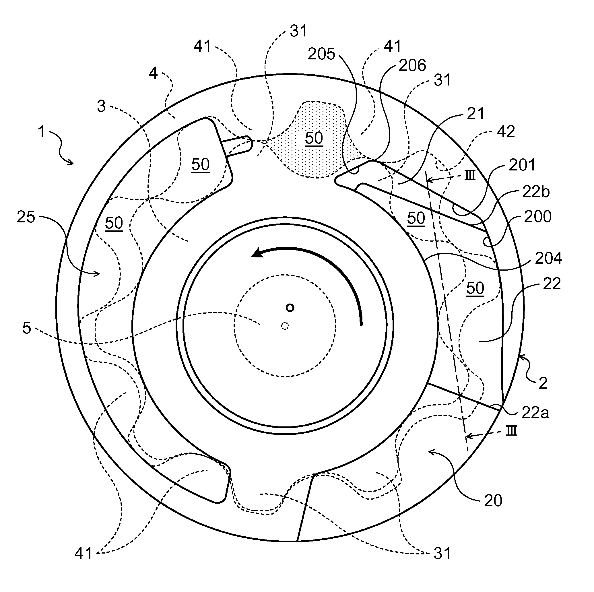
[0030]FIG. 1 is a schematic configuration diagram showing a gear pump 1 according to an exemplary embodiment. The gear pump 1 shown in the figure is mounted as an oil pump on a vehicle, not shown, and sucks hydraulic oil (ATF) stored in an oil pan (not shown) to pressure-feed the sucked hydraulic oil to a hydraulic control device (not shown). The gear pump 1 includes a pump housing 2 formed by a pump body that is fixed to, e.g., a transmission case of an automatic transmission and a pump cover that is fastened to the pump body, and an inner rotor 3 and an outer rotor 4 which are rotatably placed in a gear accommodating chamber defined by the pump housing 2.

[0031]The inner rotor 3 is coupled to a rotary shaft 5 that is connected to a crankshaft of an engine (both not shown) mounted on the vehicle, not shown, and is driven to rotate by power that is applied to th...


PUM


Abstract

In a gear pump, an outer inner wall surface of a suction port which is located on a downstream side in a rotor rotation direction, that is, a first inner wall surface, is located inward of a bottom land between internal teeth of an outer rotor, and the suction port has a shallow portion extended inward from the first inner wall surface on the downstream side in the rotor rotation direction, and a deep portion that is formed so as to be continuous with the shallow portion and that is deeper than the shallow portion. Communication between an inter-tooth chamber and the suction port is cut off with the inter-tooth chamber facing only the shallow portion.

Description

TECHNICAL FIELD[0001]The subject matter described herein relates to gear pumps including an inner rotor that has a plurality of external teeth and that is driven to rotate, and an outer rotor that has a plurality of internal teeth and that is placed so as to be offset with respect to the inner rotor.BACKGROUND ART[0002]Conventionally, a gear pump having a separation protrusion that separates an downstream end of a suction port into an inner end facing external teeth of an inner rotor and an outer end facing internal teeth of an outer rotor, a shallow flat surface formed to have a greater length in the circumferential direction as it extends closer to the outside in the radial direction from a protruding end portion of the separation protrusion, and a tilted bottom surface connected to an upstream edge of the shallow flat surface is known as this type of gear pump (see, e.g., Patent Document 1). In this gear pump, liquid that flows from the outer end of the suction port into the inte...

Claims


Application Information

Patent Timeline
Patent Type & Authority Patents(United States)
IPC IPC(8): F03C4/00F04C2/08F04C2/14F04C15/00F04C2/00F04C2/10F04C15/06F04C18/00
CPCF04C2/14F04C2/088F04C2/102F04C15/0049F04C15/06F04C2/086F04C2250/101F04C2250/102
Inventor TORII, TAKAHIRONOMURA, KENGOTODO, MINORUIWASE, MIKIOOTA, KOJITAKEDA, MITSUHIROOKOSHI, NAOKIUCHIDA, TAKUMI
Owner AISIN AW CO LTD
Why Eureka
Try Eureka