Method for controlling an electro-surgical HF generator and electro-surgical device

Active Publication Date: 2017-03-07
ERBE ELEKTROMEDIZIN GMBH
View PDF13 Cites 0 Cited by
  • Summary
  • Abstract
  • Description
  • Claims
  • Application Information

AI Technical Summary

Benefits of technology

[0008]It is an object of the present invention, to disclose a method or an electro-surgical devi

Problems solved by technology

This in turn results in a direct reduction in the electrical interference on patient monitors, video

Method used


Image

  • Method for controlling an electro-surgical HF generator and electro-surgical device
  • Method for controlling an electro-surgical HF generator and electro-surgical device
  • Method for controlling an electro-surgical HF generator and electro-surgical device

Examples


Embodiment Construction

[0020]In the following description, the same reference numerals denote the same parts or parts having similar functions.

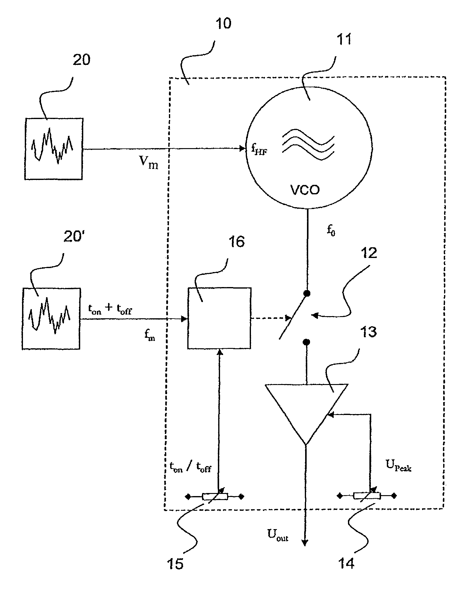
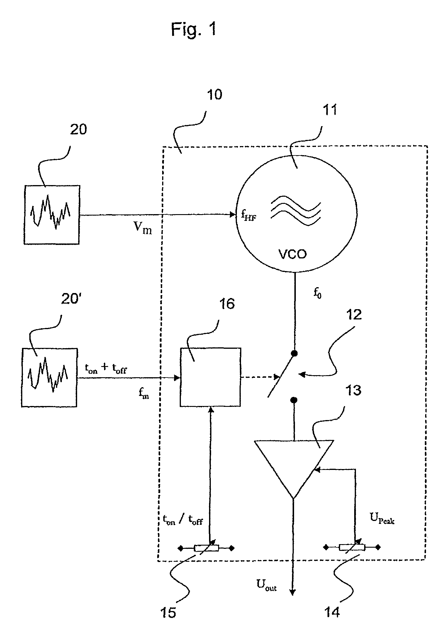
[0021]FIG. 1 is a schematised drawing of an embodiment of an electro-surgical device according to the present invention. Details of this type of known electro-surgical device may be found, for example, in DE 199 43 792 C2, DE 100 46 592 C2, EP 0 430 929 B1 or EP 0 653 192 B1, to which express referral is made here, the specifications of which are incorporated by reference herein in their entirety.

[0022]An electro-surgical device of this kind comprises a high-frequency generator 10 which encompasses an oscillator 11, the output signal of which with the frequency f0 is switched via a switch 12 and amplified by an output amplifier 13 so that an output signal Uout is present at the output of the HF generator 10. Here, it is stressed that this is a schematic representation to explain the mode of operation of the arrangement.

[0023]To adjust the output amplitude Upeak, an...


PUM


Abstract

In an electro-surgical high-frequency generator, the signal frequency or the modulation frequency or a clock frequency or any combination thereof are modulated using a low-frequency modulation signal in such a way that the spectra thereof are widened. This results in a reduction of interference on peripheral devices.

Description

BACKGROUND OF THE INVENTION[0001]The invention relates to a method for controlling an electro-surgical high-frequency (“HF”) generator and an electro-surgical device.[0002]Modern surgery frequently makes use of electro-surgical devices including a high-frequency generator for generating a high-frequency alternating current. This high-frequency alternating current is then used to cut or coagulate biological tissue or treat it in some other way.[0003]The fundamental frequency of the HF generator is usually between 300 kHz and 4 MHz. Depending upon the application, this high-frequency is modulated in different ways with respect to its amplitudes. Usually, pulse duration modulation is performed in order to determine the power applied. Here, the ratio of burst-type signal segments to succeeding pauses is set. The clock frequency or modulation is usually performed with frequencies of between 1 kHz and 50 kHz.[0004]In addition, further modulation (switching the output signal on and off) is...

Claims


Application Information

Patent Timeline
IPC IPC(8): A61B18/12A61B18/00
CPCA61B18/1206A61B2018/00732
Inventor SELIG, PETER
Owner ERBE ELEKTROMEDIZIN GMBH
Why Eureka
Try Eureka