Laser beam ophthalmological surgery method and apparatus

a laser beam and ophthalmological surgery technology, applied in the field of refractive eye surgery, can solve the problems of requiring significant effort for the surgeon to precisely align the beam, the bulky cabinet of the laser cabinet, and the inability of most advanced three-dimensional eye tracking systems to guide the laser beam to normal incidence, etc., to achieve the effect of facilitating surgery observation, reducing visible light noise, and enhancing image quality and processing capability

Active Publication Date: 2017-03-14
EXCELSIUS MEDICAL CO LTD
View PDF8 Cites 28 Cited by
  • Summary
  • Abstract
  • Description
  • Claims
  • Application Information

AI Technical Summary

Benefits of technology

[0011]A laser ophthalmological surgery apparatus uses a method of ablating eye tissue which includes generating a UV laser beam, such as an excimer laser, and directing the generated laser beam through a manually activated shutter, a homogenizer and a rotating mirror set module so the laser beam enters the hand piece module at normal incidence to its entrance plane. In the hand piece module, the laser beam passes through a two dimensional scanner (piezo tip / tilt scanner or galvanometer set) and is converted to a two dimensional random overlapping scanning diverging laser beam. A computer generates the random scanning pattern signal, for controlling the scanner to produce the two dimensional random overlapping scanning pattern from the input laser beam. The laser beam then passes through an f-theta telecentric scan focusing lens to convert the laser beam into a two dimensional overlapping randomly scanned parallel laser beam. A dielectric mirror deflects the laser beam as it exits the hand piece module and onto the patient's eye. The hand piece module has an eye stabilization and distance control unit with an open center area used to align the eye to the hand piece via direct contact. The selected hand piece also has at least one or more (typically four) near infrared illumination lights mounted on the hand piece for aligning the eye stabilization and distance control member to a patient's eye and a video camera attached to facilitate surgery observation. The generated laser beam exits the hand piece module through the open center of the eye stabilization and distance control member. The hand piece module is connected to the end of the rotating mirror set module and moved to align the eye stabilization and distance control unit into contact with a patient's eye. The hand piece is aligned utilizing a microscope. There is an alignment hole above the dielectric mirror that allows the user to center the eye stabilization and distance control member on the patient's pupil using the microscope through the alignment hole. A visible light beam directed through the microscope and alignment hole is used to guide the patient's eye focus at normal incidence to the hand piece. There is a hot mirror placed above the dielectric mirror under the alignment hole to guide the near infrared reflecting light to the video camera and enhance image quality and processing capability by reducing visible light noise for the video camera. The laser beam is then impinged onto the surface of the patient's eye responsive to activation of the shutter to ablate tissue from the surface of the patient's eye. Thus surgical ablation is performed on a patient's eye with a two dimensional overlapping randomly scanned parallel laser beam through a hand manipulated hand piece in contact with the patient's eye.

Problems solved by technology

In this case, the laser cabinet is bulky and a fixed laser delivery arm is used to transfer the laser beam into a random scanning pattern onto the cornea.
Most of the modern laser systems employ an eye tracker system to follow eye movement but even the most advanced three dimensional eye tracking system cannot guide the laser beam to normal incidence upon the corneal surface due to the rotational nature of the eye ball.
This requires significant effort for the surgeon to precisely align the beam with the eye.
A flexible articulated mirror arm lengthens and complicates the UV laser's path and is not an obvious solution to current refractive surgery problems.
Placing lenses in an optical arm amplifies alignment errors and creates a more complex module.

Method used


Image

  • Laser beam ophthalmological surgery method and apparatus
  • Laser beam ophthalmological surgery method and apparatus
  • Laser beam ophthalmological surgery method and apparatus

Examples


Embodiment Construction

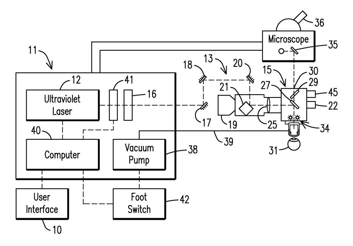
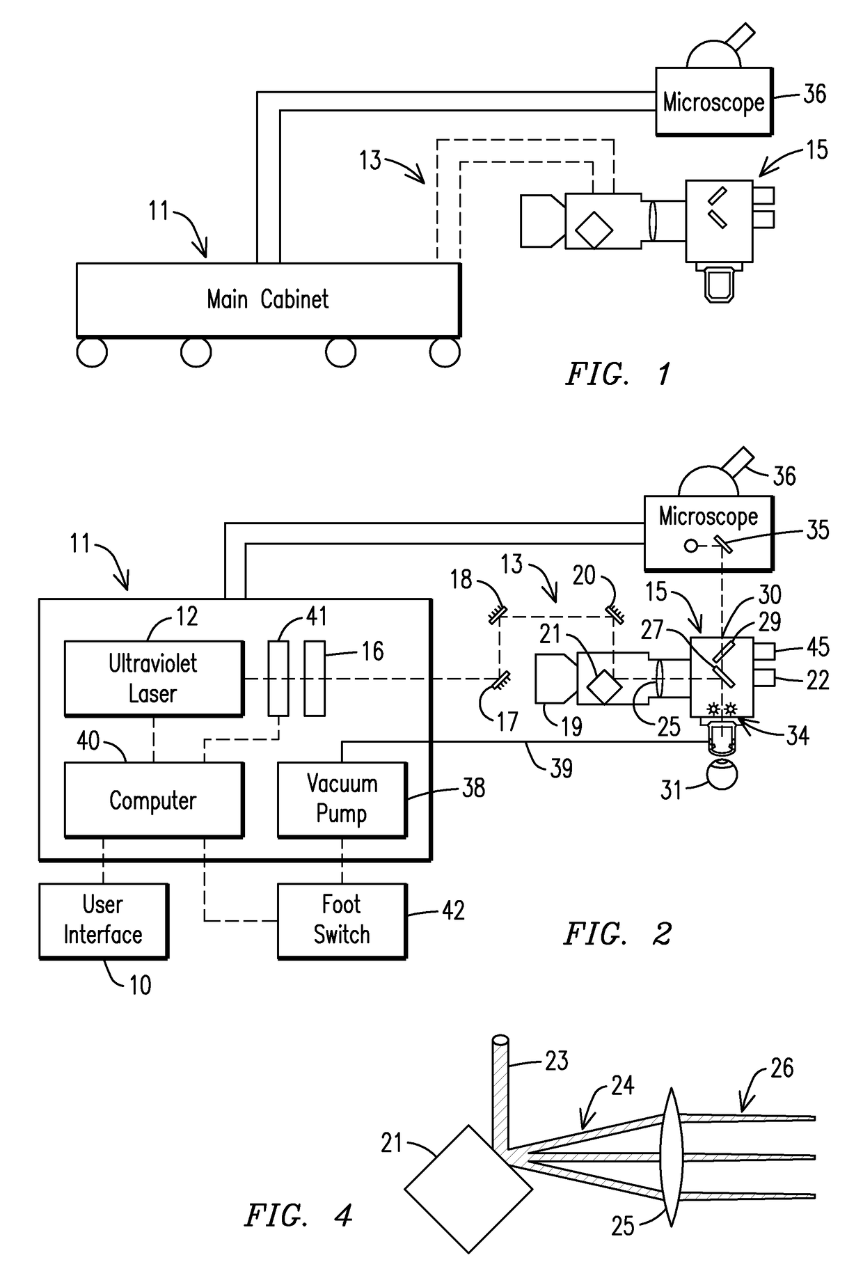
[0020]The laser ophthalmological surgery apparatus in accordance with the present invention as seen in the drawings, FIGS. 1 through 6, includes a user interface 10, in FIG. 2, connected to a main cabinet 11. Within the main cabinet, laser pulses are generated with UV laser 12 that is guided through an attached rotating mirror set module 13. The ophthalmological apparatus has a main cabinet and a hand piece module 15 connected to either end of the rotating mirror set module. The UV laser is positioned in the main cabinet 11 and has a laser beam output of laser pulses. A laser beam homogenizer 16 is positioned to homogenize the laser beam to smooth out irregularities in the laser beam before it is directed through the rotating mirror set module.

[0021]A method of ablating eye tissue, as illustrated in FIGS. 2 through 4, generates a pulse laser beam from an UV laser 12. The laser beam passes through the rotating mirror set module 13 having mirrors 17, 18, 20 (for demonstration; can hav...


PUM


Abstract

This invention is related to refractive eye surgery and specifically regarding guiding a laser beam through free space using a set of rotatable mirrors to guide said laser beam into a hand piece module that converts the laser beam into a two dimensional random overlapping scanning parallel laser beam that is delivered to the eye for ablation of cornea tissue to reshape the cornea of the eye. The rotating mirror set module allows a hand piece having an eye stabilization and distance control unit to be positioned by the surgeon onto a patient's eye for performing the surgery.

Description

[0001]This patent application is a continuation-in-part application of my pending U.S. patent application Ser. No. 13 / 404,127, filed Feb. 24, 2012 for LASER BEAM OPHTHALMOLOGICAL SURGERY METHOD AND APPARATUS.BACKGROUND OF THE INVENTION[0002]This invention is related to refractive eye surgery and specifically regarding guiding a laser beam through free space using a set of rotatable mirrors into a hand piece module that converts the laser beam into a two dimensional random overlapping scanning parallel laser beam that is delivered to the eye for ablation of cornea tissue to reshape the cornea of the eye.[0003]About three-quarter of the refractive power of the eye is determined by the curvature of the anterior surface of the cornea and changing the shape of the cornea offers a way to significantly reduce or eliminate refractive errors of the eye. The stroma is thick enough that portions of its anterior region can be ablated away to change its profile and thus change the refractive pow...

Claims


Application Information

Patent Timeline
Patent Type & Authority Patents(United States)
IPC IPC(8): A61F9/008
CPCA61F9/00804A61F2009/00872A61F2009/00897
Inventor HUANG, CHENG-HAO
Owner EXCELSIUS MEDICAL CO LTD
Why Eureka
Try Eureka