Heat dissipation structure and optical transceiver

a technology optical transceiver, which is applied in the direction of cooling/ventilation/heating modifications, instruments, and modifications by conduction heat transfer, can solve the problems of heat dissipation structure that dissipates achieves efficient dissipation of heat of optical distributors, increase the heat generation density of optical distributors, and increase the heat dissipation efficiency.

Inactive Publication Date: 2017-03-14
MITSUBISHI ELECTRIC CORP
View PDF28 Cites 0 Cited by
  • Summary
  • Abstract
  • Description
  • Claims
  • Application Information

AI Technical Summary

Benefits of technology

[0009]According to the invention, since it is configured as described above, a heat dissipation efficiency thereof is increased due to an increase in a contact area between the heat transfer part and the casing to thereby efficiently dissipate the heat of the optical distributor. As a result, it is possible to achieve an increase in the heat generation density of the optical distributor, a reduction in size of the casing, and enlargement of an operating temperature range to a temperature increase.

Problems solved by technology

In a device that performs optical communications (optical distributor), a heat generation density is increased in order to respond to market needs for an improvement in performance and a reduction in size, and thus, a heat dissipation structure that dissipates heat of the optical distributor poses a problem.

Method used


Image

  • Heat dissipation structure and optical transceiver
  • Heat dissipation structure and optical transceiver
  • Heat dissipation structure and optical transceiver

Examples


embodiment 1

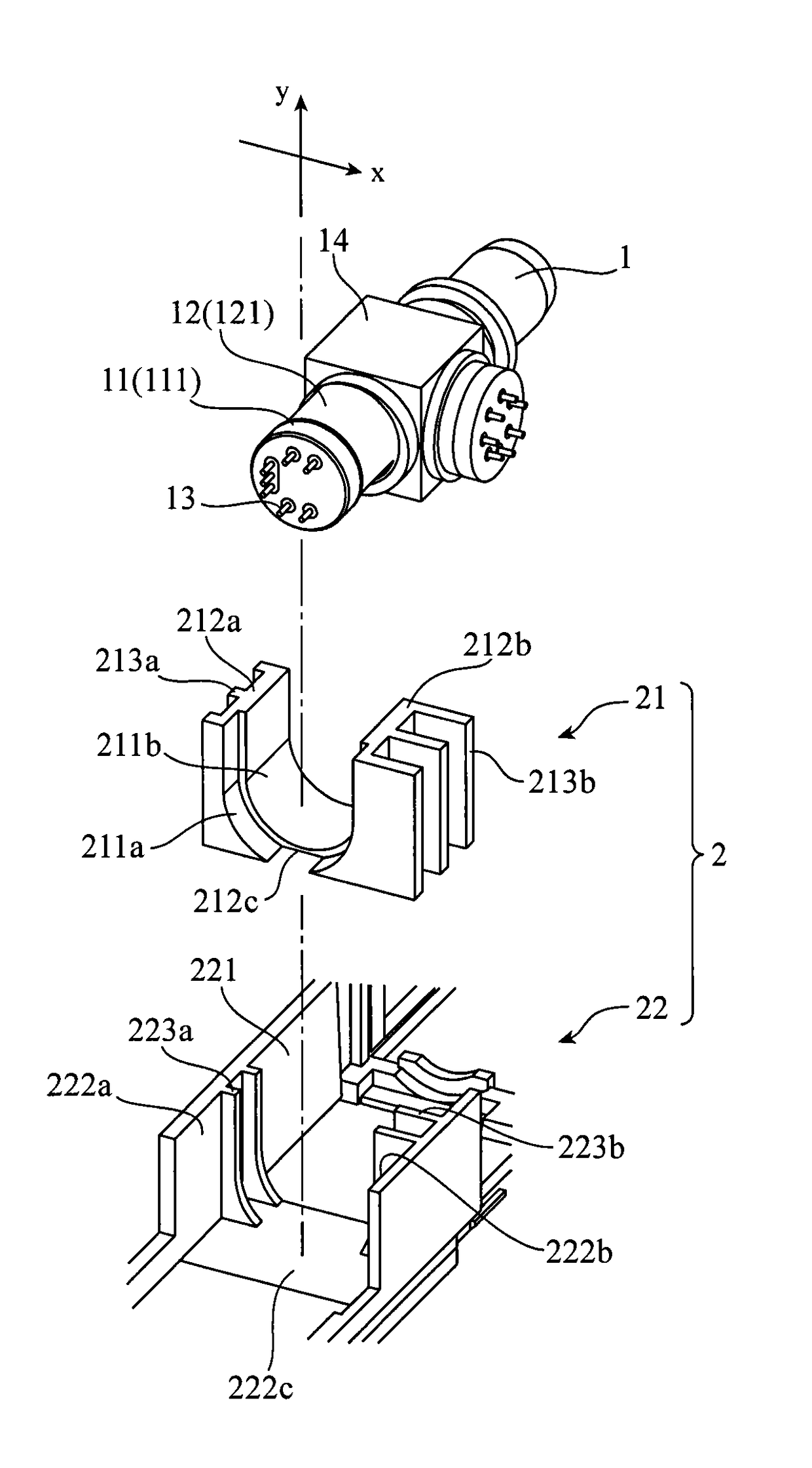
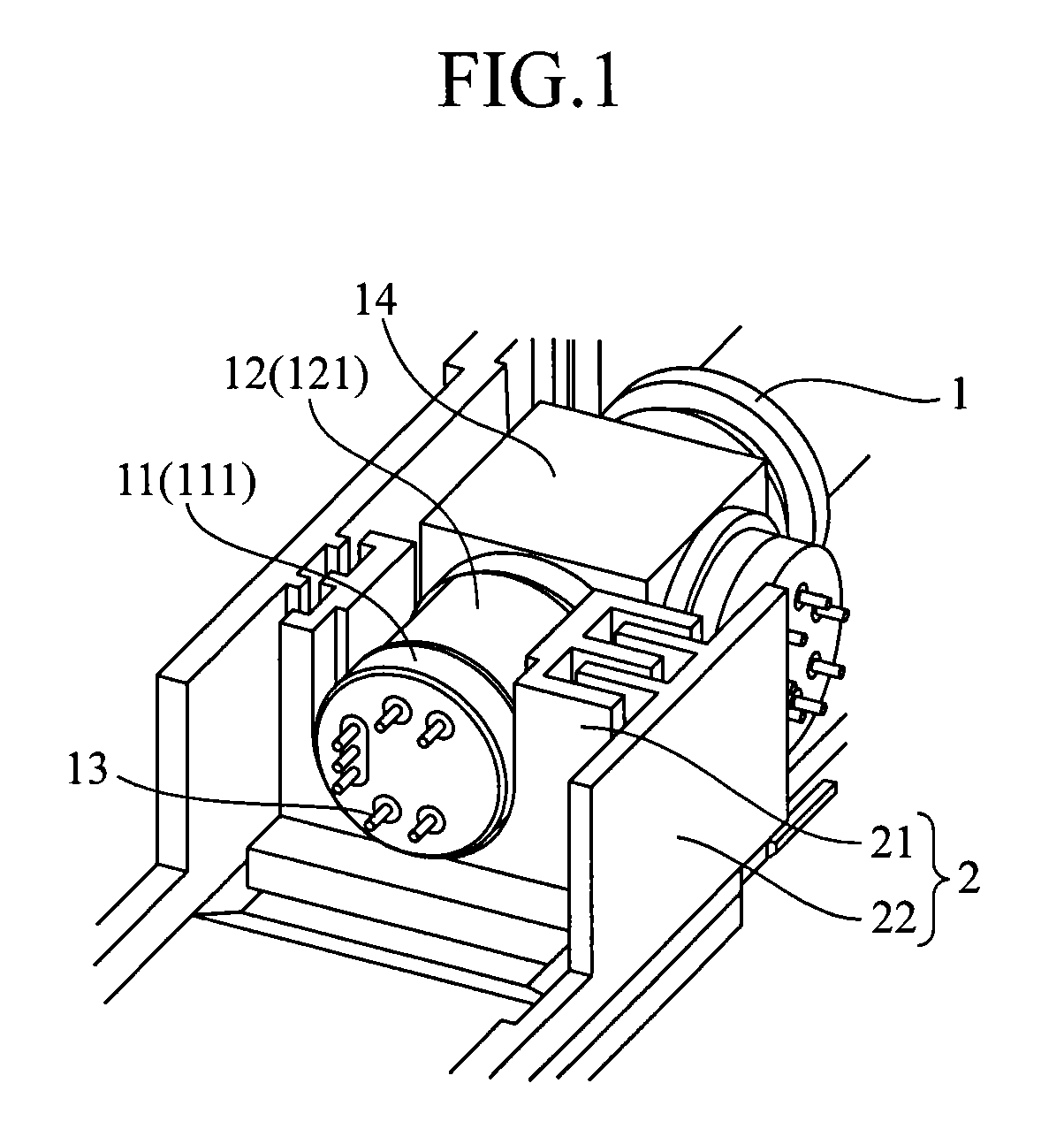
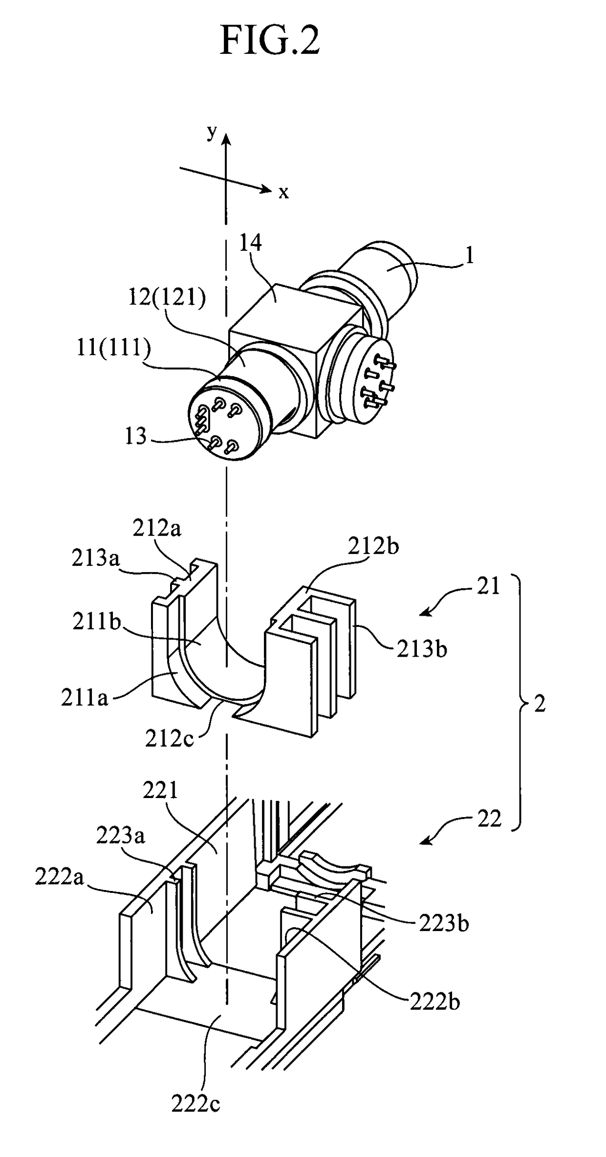
[0023]FIG. 1 is a perspective view showing a configuration of a heat dissipation structure 2 according to Embodiment 1 of the present invention, and FIG. 2 is an exploded perspective view thereof. FIG. 1 shows a state in which an optical distributor 1 is accommodated in the heat dissipation structure 2.

[0024]First, a configuration of the optical distributor 1 will be described.

[0025]The optical distributor 1 has a CAN type package, and contains a semiconductor optical element (not shown) that generates heat. Examples of the semiconductor optical element include a semiconductor laser element (laser diode) and the like. Additionally, the optical distributor 1 may also contain a light receiving element.

[0026]As shown in FIGS. 1 and 2, the optical distributor 1 has a disk-like stem 11 on which the semiconductor optical element is to be mounted and a cylindrical part 12 made of a metal that covers the semiconductor optical element on the stem 11. In addition, a plurality of lead pins 13 ...

embodiment 2

[0049]In Embodiment 2, there is shown a case where by using the cylindrical shapes of the stem 11 and the cylindrical part 12, the projected and retracted portions 213a and 213b of the heat transfer part 21 and the projected and retracted portions 223a and 223b of the casing 22 are formed in curved surface shapes conforming to the corresponding cylindrical shapes.

[0050]FIG. 7 is a perspective view showing a configuration of a heat dissipation structure 2 of an optical distributor 1 according to Embodiment 2 of the present invention, and FIG. 8 is an enlarged cross-sectional view taken along a line A-A of FIG. 7. In FIGS. 7 and 8, the same components as those of the heat dissipation structure 2 according to Embodiment 1 shown in FIGS. 1 and 2 are designated by the same reference numerals, and only different parts will be explained.

[0051]As shown in FIG. 8, the cross sections of the projected and retracted portions 213a and 213b of the heat transfer part 21 in Embodiment 2 that are su...

embodiment 3

[0053]In each of Embodiments 1 and 2, there is shown the case where the heat-dissipating surfaces 212a and 212b of the heat transfer part 21 and the heat-receiving surfaces 222a and 222b of the casing 22 are provided with the projected and retracted portions 213a, 213b, 223a, and 223b. In contrast to this, in Embodiment 3, there is shown a case where the heat-dissipating surface 212c of the heat transfer part 21 is provided with groove portions 214a and 214b, and the heat-receiving surface 222c of the casing 22 is provided with projected portions 224a and 224b that are engaged with the groove portions 214a and 214b.

[0054]FIG. 9 is an exploded perspective view showing a configuration of a heat dissipation structure 2 of an optical distributor 1 according to Embodiment 3 of the present invention. Note that in FIG. 9, the depiction of the optical distributor 1 is omitted. In FIG. 9, the same components as those of the heat dissipation structure 2 according to Embodiment 1 shown in FIG...


PUM


Abstract

There are provided a heat transfer part 21 having heat-receiving surfaces 211a and 211b which have curved surface shapes along side surfaces 111 and 121 of a stem 11 and a cylindrical part 12 and in which the stem 11 and the cylindrical part 12 can be fitted, and heat-dissipating surfaces 212a and 212b provided with projected and retracted portions 213a and 213b; and a casing 22 having the optical distributor 1 and the heat transfer part 21 mounted thereon, and having heat-receiving surfaces 222a and 222b provided with projected and retracted portions 223a and 223b engaged with the projected and retracted portions 213a and 213b.

Description

TECHNICAL FIELD[0001]The present invention relates to a heat dissipation structure that dissipates heat of an optical distributor having a stem on which a semiconductor optical element is mounted and a cylindrical part that covers the semiconductor optical element on the stem, and relates to an optical transceiver that includes the optical distributor and the heat dissipation structure.BACKGROUND ART[0002]In a device that performs optical communications (optical distributor), a heat generation density is increased in order to respond to market needs for an improvement in performance and a reduction in size, and thus, a heat dissipation structure that dissipates heat of the optical distributor poses a problem.[0003]Accordingly, for example, in a technique disclosed in Patent Document 1, a heat dissipation structure that uses a difference in thermal conductivity between a resin and a metal is mounted to an optical distributor. In this heat dissipation structure, a stem of the optical ...

Claims


Application Information

Patent Timeline
Patent Type & Authority Patents(United States)
IPC IPC(8): G02B6/42H05K7/20G02B6/38
CPCG02B6/4269G02B6/4246H05K7/2039G02B6/3873G02B6/4201G02B6/4204
Inventor GOTO, HIDEKIHIMURA, NAOTOTANI, NORIYUKIHAGA, SEIJITAMURA, MASAYOSHI
Owner MITSUBISHI ELECTRIC CORP
Why Eureka
Try Eureka