
Self-testing auto monitor ground fault circuit interrupter (GFCI) with power denial

a fault circuit interrupter and self-monitoring technology, applied in the direction of electronic protection circuit testing, protective switch details, instruments, etc., can solve the problems of device unable to properly detect the ground fault and/or properly interrupt the flow of electrical current, and remove all power from the load

Active Publication Date: 2017-03-14
HUBBELL INC
View PDF5 Cites 2 Cited by
  • Summary
  • Abstract
  • Description
  • Claims
  • Application Information

AI Technical Summary

Benefits of technology

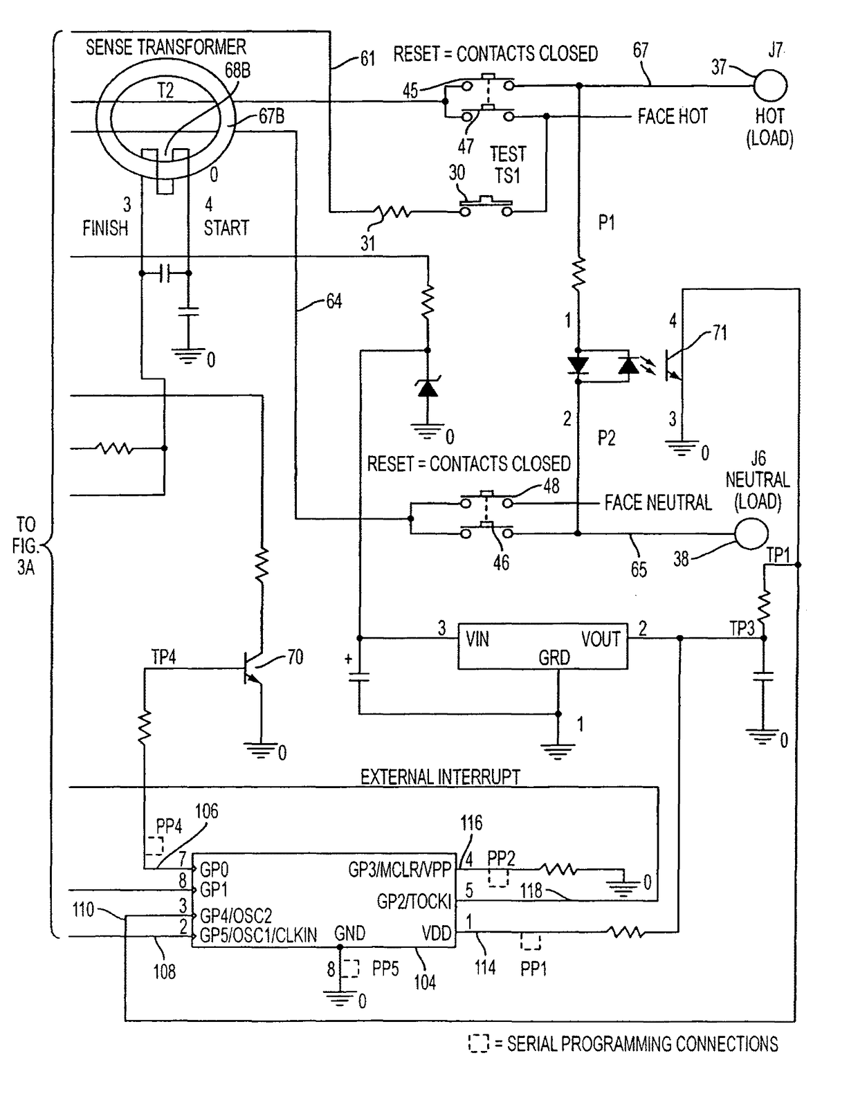
The GFCI device described in this patent is designed to automatically test its ability to detect ground faults or malfunctions without interfering with its normal functioning. The device performs the automatic test within five seconds of power availability and repeatedly over at least three hours. An end-of-life indicator is also included to alert when the device has failed to properly detect the test signal. This unique monitoring circuit takes advantage of the filtering capabilities of the device and prevents false tripping under normal conditions.

Problems solved by technology

The fault condition can result when a person comes into contact with the hot side of the AC load and an earth ground, a situation which can result in serious injury.
When such an imbalance is detected, a relay or circuit breaker within the GFCI device is immediately tripped to an open condition, thereby removing all power from the load.
The latter type of connection, which may result from a defective load or from improper wiring, is potentially dangerous because it can prevent a conventional GFCI device from tripping at the required threshold level of differential current when a line-to-ground fault occurs.
Like most electro-mechanical devices, however, GFCI devices are susceptible to failure.
For example, one or more of the electronic components that drive the mechanical current interrupter device can short-out or otherwise become defective, as can components in the fault detector circuit or elsewhere within the device, rendering the device unable to properly detect the ground fault and / or properly interrupt the flow of electrical current.
A study performed by industry safety groups indicated that most often the public does not regularly test their GFCI devices for proper operation, i.e., by pressing the TEST button.
This study further revealed that some GFCI devices that had been in service for an extended period of time became non-functional and were unable to properly detect a fault condition, thus, rendering the device unsafe.
Specifically, it was discovered that after extended use GFCI devices fail to trip when a fault occurs, thus rendering the device operable as an electrical receptacle but unsafe in the presence of a fault condition.
Because the devices are not being regularly tested, this unsafe condition is exacerbated.
That is, people falsely believe the device is operational, in view of the fact that it adequately delivers power, when in fact the device is a potentially life-threatening hazard.
The discovery that GFCI devices deployed in the field are becoming increasingly non-operational and unsafe in combination with the realization that people do not regularly test their GFCI devices, regardless of manufacturer's explicit instructions to do so, initiated investigations into possible changes to the UL-943 standard to require the GFCI devices to self-test (e.g., auto-monitor) themselves without the need for human intervention.
The digital solutions offered thus far, however, are not ideal.
For example, several related art GFCI designs, including those directed at providing self-test functionality, suffer from nuisance tripping, a situation where the interrupter is actuated when neither a real ground fault, a manually generated simulated ground fault, nor an automatic self-test fault are present.
This unfavorable condition is believed by many to be worsened by the additional requirement of automatic self-testing, which results in additional inductive currents being generated within the device.

Method used


Image

  • Self-testing auto monitor ground fault circuit interrupter (GFCI) with power denial
  • Self-testing auto monitor ground fault circuit interrupter (GFCI) with power denial
  • Self-testing auto monitor ground fault circuit interrupter (GFCI) with power denial

Examples


Embodiment Construction

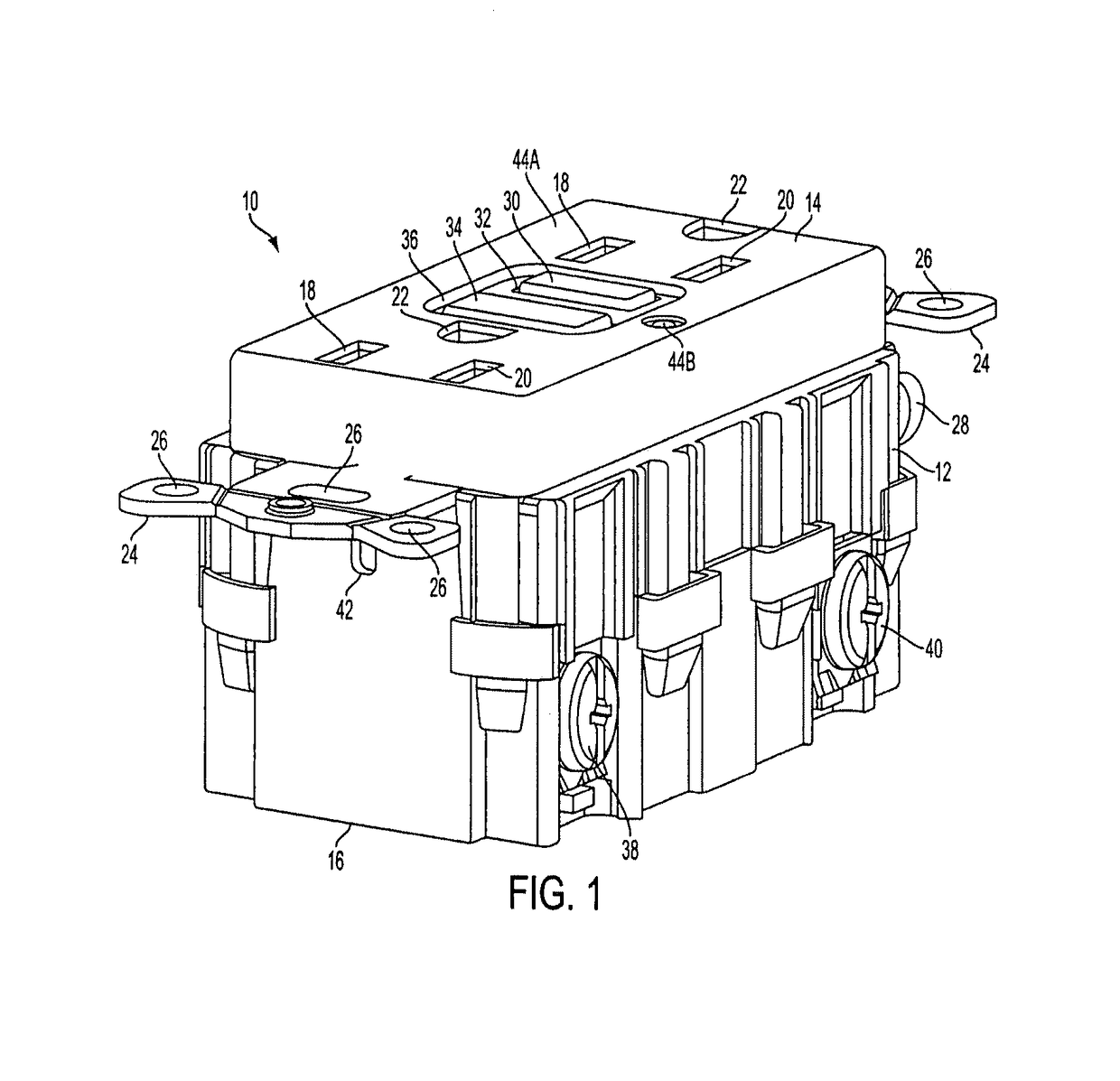
[0055]FIG. 1 is a perspective view of an example of a ground fault circuit interrupting (GFCI) device 10 in accordance with an embodiment of the present invention. The GFCI device 10 comprises a housing 12 having a cover portion 14 and a rear portion 16. The GFCI also includes an inner housing 13 (See FIG. 4) when the cover portion 14 is removed from the rear portion 16. The cover portion 14 and rear portion are removably secured to each other via fastening means such as clips, screws, brackets, tabs and the like. The cover portion includes plugin slots (also known as face receptacles) 18 and 20 and grounding slots 22. It should be appreciated by those skilled in the art that plugin slots 18 and 20 and grounding slots 22 can accommodate polarized, non-polarized, grounded or non-grounded blades of a male plug. The male plug can be a two wire or three wire plug without departing from the scope of the embodiment of the present invention.

[0056]The GFCI receptacle 10 further includes mou...


PUM


Abstract

A self-testing fault detector having a line side and a load side and a conductive path there between is provided. The self-testing fault detector includes an auto-monitoring circuit electrically coupled to a fault detection circuit and an interrupting device and it continuously monitors one or more signals to determine an operating state of the fault detector. At least one of the monitored signals includes a fault detection signal, wherein if said automonitoring circuit determines that the fault detection circuit is not properly driving the interrupting device, the automonitoring device converts an input-output port receiving the fault detection signal from an input to an output and drives the interrupting device into a tripped condition using the input-output port.

Description

CROSS-REFERENCE TO RELATED APPLICATION[0001]Related subject matter is disclosed in U.S. Pat. No. 7,443,309, filed on Dec. 1, 2004, titled “SELF TESTING GROUND FAULT CIRCUIT INTERRUPTER (GFCI)”, and U.S. patent application Ser. No. 13 / 422,793, filed on Mar. 16, 2012, titled “REINSTALLABLE CIRCUIT INTERRUPTING DEVICE WITH VIBRATION RESISTANT MISWIRE PROTECTION,” the entire respective contents of both of which are hereby incorporated by reference for all that is taught.BACKGROUND OF THE INVENTION[0002]Field of the Invention[0003]The present invention relates generally to a self-testing fault interrupting device, such as a ground fault circuit interrupter (GFCI). More particularly, the present invention relates to a self-testing fault interrupting device where a periodic self-test is performed on the fault detection and tripping portions of the device independent of a manual test.[0004]Description of Related Art[0005]Fault interrupting devices are designed to trip in response to the det...

Claims


Application Information

Patent Timeline
Patent Type & Authority Patents(United States)
IPC IPC(8): H02H3/33H01H83/04G01R31/02G01R31/28H02H3/16H02H3/04H01H71/04
CPCH02H3/335G01R31/025G01R31/2827H01H83/04H02H3/044H02H3/162H01H2071/044H01H2300/052G01R31/52G01R31/50H01H71/04
Inventor BATKO, THOMAS JAMESDEBARTOLO, JOSEPH VINCENT
Owner HUBBELL INC
Learn More