
Turbine lock plunger for ram air turbine assembly

a technology of air turbine and plunger, which is applied in the direction of rotors, marine propulsion, vessel construction, etc., can solve the problems of hammering effect, severe hlsd vibrations, and long duration wind milling vibrations driven by high unbalance load, and achieve the effect of reducing axial movemen

Active Publication Date: 2017-03-21
HAMILTON SUNDSTRAND CORP
View PDF13 Cites 1 Cited by
  • Summary
  • Abstract
  • Description
  • Claims
  • Application Information

AI Technical Summary

Benefits of technology

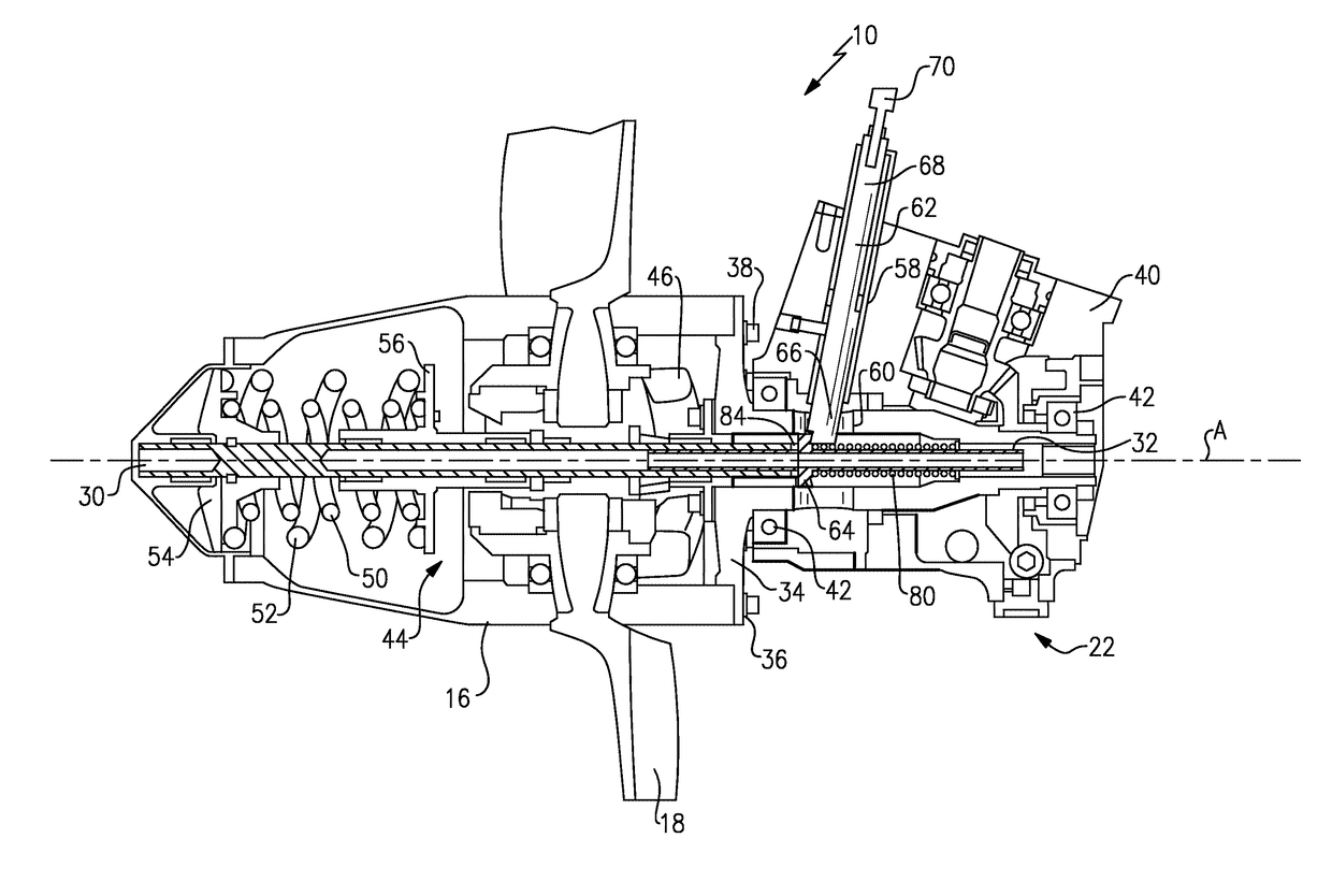
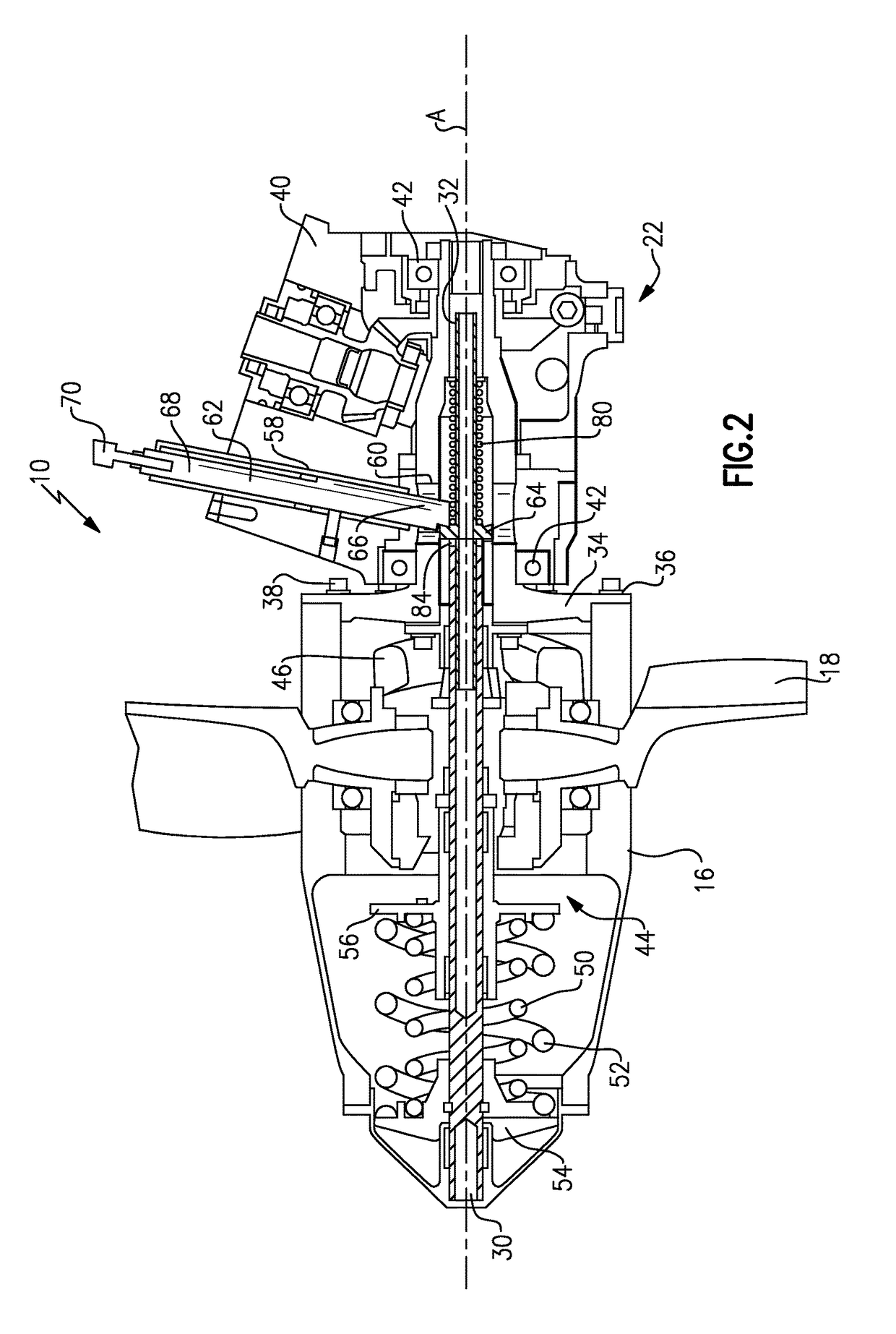
[0006]In a further embodiment of the above, the stop shaft includes an enlarged shoulder portion that provides an abutment surface for the lock plunger to reduce axial movement of the governor shaft when stowed.
[0011]In another exemplary embodiment, a ram air turbine assembly comprises a turbine including a turbine hub and a plurality of turbine blades extending outwardly from the turbine hub, and includes a support structure supporting the turbine wherein the support structure is movable between a stowed position and a deployed position. A governor shaft is positioned within the turbine hub and defines an axis of rotation. A stop shaft is coupled for rotation with the governor shaft and a rotatable housing portion surrounds at least a portion of the stop shaft. A lock plunger is configured to extend through an opening in the rotatable housing portion to prevent rotation of the rotatable housing portion when in the stowed position

Problems solved by technology

However, when in the stowed position, vibrations can overcome the start spring preload which can cause the components to hammer axially inside the turbine as a result of the axial free play.
Engine wind milling vibrations, high level short duration (HLSD) vibrations, or random vibrations can cause this hammering effect.
During an aircraft engine blade loss event, severe HLSD vibrations occur first as the engine spools down.
Then, as the engine continues to turn due to air loads, a high unbalance load continues to drive longer duration wind milling vibrations.
Either or both of these vibrations could significantly reduce the fatigue life of ram air turbine components.
However, HLSD vibrations are high level resonant vibrations where one or more ram air turbine modes are excited to resonance as the engine spools down resulting in high loads through the ram air turbine housings.

Method used


Image

  • Turbine lock plunger for ram air turbine assembly
  • Turbine lock plunger for ram air turbine assembly
  • Turbine lock plunger for ram air turbine assembly

Examples


Embodiment Construction

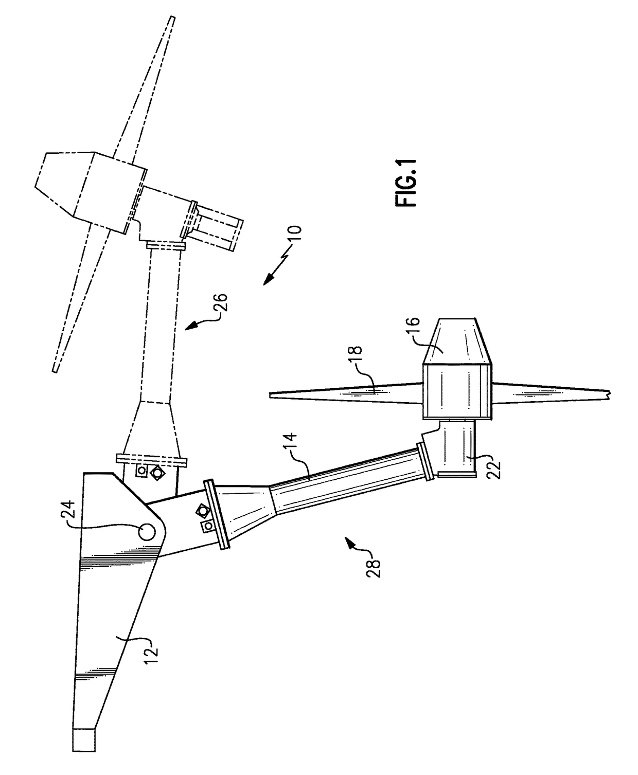
[0021]FIG. 1 schematically illustrates a ram air turbine assembly 10 that includes a deployable support structure 14 pivotally attached to an aircraft structure 12. A rotating turbine hub 16 includes turbine blades 18 and is supported on a distal end of the support structure 14. The rotating hub 16 is supported on a housing 22 attached to the end of the support structure 14. The support structure 14 is movable about a pivot 24 between a stowed position 26 and a deployed position 28.

[0022]The example ram air turbine assembly 10 is shown and described by way of example, and other configurations and structures are within the contemplation of this invention. For example, U.S. patent application Ser. No. 13 / 430,890, filed on Mar. 27, 2012, assigned to the same assignee as the present application and herein incorporated by reference, shows another example of a ram air turbine arrangement.

[0023]Further, the example ram air turbine assembly 10 operates to provide auxiliary power generation ...


PUM

PropertyMeasurementUnit
axial movementaaaaaaaaaa
diameteraaaaaaaaaa
axial lengthaaaaaaaaaa

Abstract

A ram air turbine assembly includes a governor shaft rotatable about an axis and a stop shaft coupled for rotation with the governor shaft. A rotatable housing portion surrounds at least a portion of the stop shaft. A lock plunger extends through an opening in the rotatable housing portion to prevent rotation of the rotatable housing portion and minimize vibration impact loading when stowed.

Description

BACKGROUND OF THE INVENTION[0001]This disclosure relates to a ram air turbine assembly that includes a lock plunger that prevents the turbine from rotating when stowed, as well as reducing the axial play of various turbine components when stowed.[0002]A typical ram air turbine assembly includes a turbine supported by a support structure that is movable between a stowed position and a deployed position. The turbine encloses a governor assembly within a turbine hub. A rotating housing portion is connected to the turbine hub and a non-rotating housing is connected to the support structure. A lock plunger is used to prevent the turbine from rotating when in the stowed position.[0003]The governor components are configured to have a certain amount of axial free play when in the deployed position. The governor components are preloaded in a start position by a relatively low force start spring, i.e. a 50 pound preload, for example. However, when in the stowed position, vibrations can overco...

Claims


Application Information

Patent Timeline
Patent Type & Authority Patents(United States)
IPC IPC(8): F01D25/28
CPCF01D25/28F05D2220/34Y10T29/4932
Inventor BANNON, DAVID G.RUSS, DAVID E.
Owner HAMILTON SUNDSTRAND CORP
Learn More