Magnetic resonance imaging method and apparatus

a magnetic resonance imaging and magnetic field technology, applied in the direction of magnetic measurement, measurement using nmr, instruments, etc., can solve the problem that the spatial resolution of recorded images using such technologies is limited, and achieve the effect of facilitating subsequent medical applications, extending scanning range, and clear arrangemen

Active Publication Date: 2017-03-21
SIEMENS HEALTHCARE GMBH
View PDF17 Cites 1 Cited by
  • Summary
  • Abstract
  • Description
  • Claims
  • Application Information

AI Technical Summary

Benefits of technology

[0026]This can have advantageous effects for the MR overall image. For example, the MR overall image can have straight edges or well-defined borders. This can make a subsequent medical application easier and result in a clearer arrangement.
[0027]The technologies described above allow for an adjustment of the dimensions of the MR scanning ranges along the first direction and / or second direction and / or third direction. It should be understood that for composing the MR overall image from MR partial images of the respective MR scanning ranges, it would be advantageous when the adjacent MR scanning ranges are sufficiently overlapping. As a result, it can be assured that the adjacent MR scanning ranges are correctly composed during the composition process.
[0028]Furthermore, the method can include for all MR scanning ranges, implementing a threshold value comparison that compares an overlap along the first direction of the respective MR scanning range with adjacent scanning ranges using a predetermined overlap threshold. In addition, depending on the threshold value comparison, the method can include the selective extension of the length along the first direction for all MR scanning ranges.
[0029]For example, the overlap can be defined as the region that includes the respective MR scanning range and the adjacent MR scanning range (intersection). The extension can take place such that the extended overlap is greater than or equal to the overlap threshold value. For this purpose, the scanning range can be extended by a difference length. The extension can take place separately or collectively for adjacent MR scanning ranges that are arranged along the first direction on the left and right side (here, and subsequently any desired definition) in relation to the central point.
[0030]For example, the threshold value comparison can be performed separately for the adjacent MR scanning ranges that are arranged along the first direction on the left or right side in relation to the central point of the respective MR scanning range. Correspondingly, the selective extension along the first direction can be performed for the respective MR scanning ranges by different difference lengths on the left or right side in relation to the central point. As a result, especially the central point of the respective MR scanning range can be shifted through the selective extension along the first direction. However, it is also possible to perform the selective extension along the first direction in such a way that the position of the central point remains basically constant: for example, the selective extension could be performed along the first direction with equal difference lengths on the left and right side in relation to the central point. For example, the difference length can be selected to be equal to the greater of the two difference lengths.
[0031]By selectively extending the length along the first direction, it can be ensured that the composition of the MR overall image from the MR partial images can always resort to a sufficiently great overlap between adjacent MR partial images. This can increase the precision of the composition.

Problems solved by technology

However, it is important to understand that typically the MR overview image that is recorded with such technologies has only a limited spatial resolution and can be used only in a limited manner for subsequent diagnostics or other medical applications.

Method used


Image

  • Magnetic resonance imaging method and apparatus
  • Magnetic resonance imaging method and apparatus
  • Magnetic resonance imaging method and apparatus

Examples


Embodiment Construction

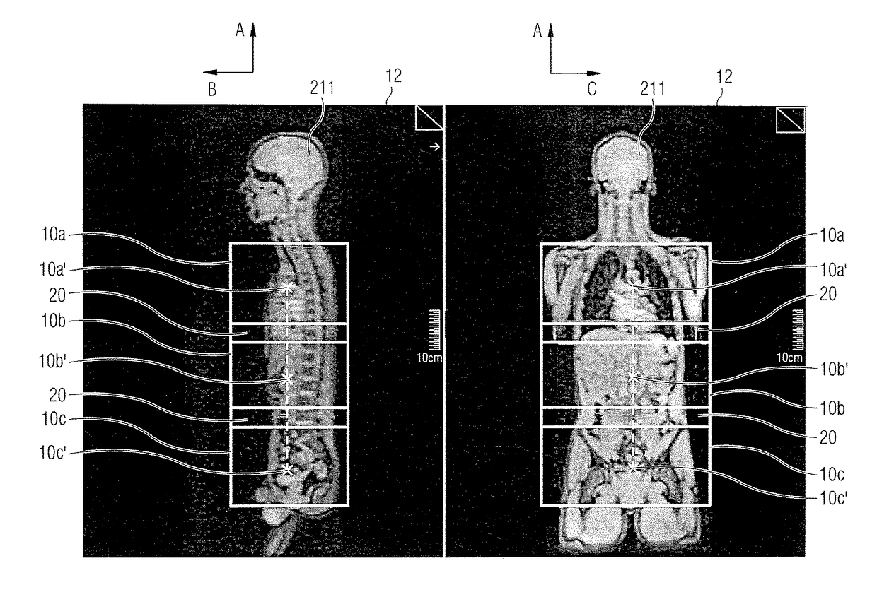
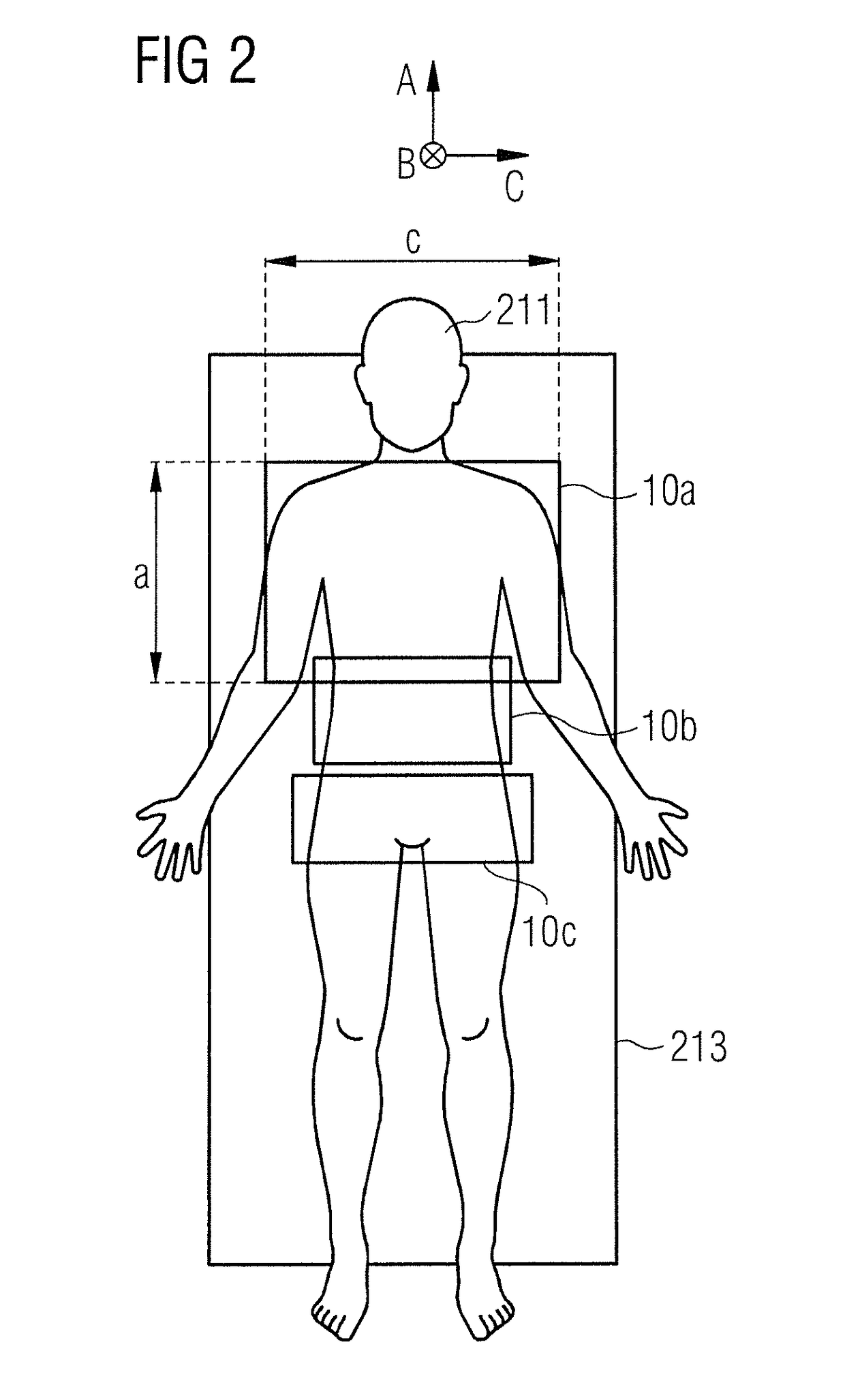
[0057]The present invention is described in more detail by means of preferred embodiments with reference to the drawings. The different embodiments relate to technologies which allow for automatic planning and for a performance of whole-body MR imaging or multi-station MR imaging. For this purpose, the MR scanning ranges are determined in relation to the anatomic characteristics of a patient and then geometrically adjusted to one another. The MR scanning ranges define the areas of the patient for which subsequently MR partial images are to be recorded. Then, the MR partial images are composed to an MR overall image. Corresponding reference numerals in the figures describe corresponding or similar elements.

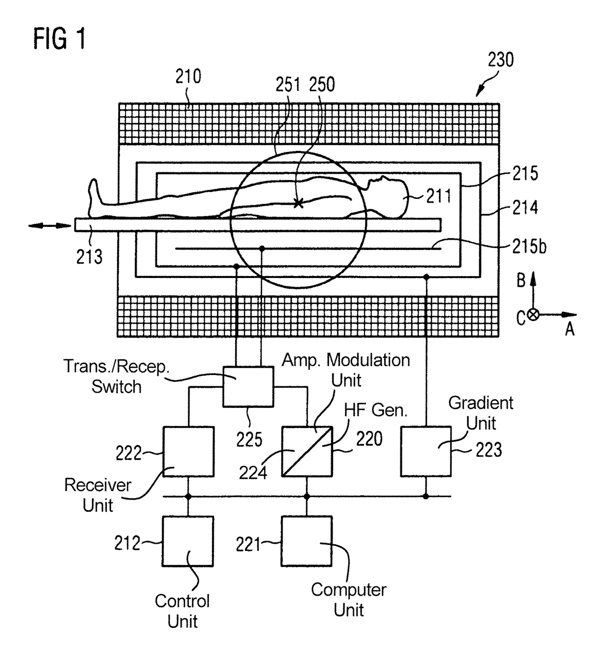
[0058]FIG. 1 shows a schematic view of a magnet resonance (MR) system 230 according to an embodiment of the present invention. The MR system 230 comprises a magnet 210 for generating a basic magnetic field. For example, the magnet 210 can involve a tubular magnet and the basic magn...


PUM


Abstract

In a method and apparatus for automatic magnetic resonance imaging of a patient, an MR overall image is composed from several MR partial images. An MR overview image is received by a process that determines several scanning ranges based on the MR overview image. The MR scanning ranges are characterized by a length along a first direction. For all MR scanning ranges: the length along the first direction is set equal to the length of the longest MR scanning range in the first direction.

Description

BACKGROUND OF THE INVENTION[0001]Field of the Invention[0002]The present invention concerns techniques for automatic magnetic resonance imaging in which a magnetic resonance overall image is composed of several magnetic resonance partial images. In particular, the invention concerns such techniques that allow for an automatic determination of various magnetic resonance scanning ranges respectively for which a magnetic resonance partial image is recorded.[0003]Description of the Prior Art[0004]In recent years, magnetic resonance (MR) tomography has been established as an important imaging modality for examining objects, especially in medical diagnostics. For this purpose, magnetic moments (spins) of nuclei are deflected from their rest position (which typically lies parallel to a basic magnetic field of several Tesla) by irradiating radio-frequency (RF) pulses, and the signal emitted during relaxation of the spins is used for imaging. A special application area of MR imaging is the r...

Claims


Application Information

Patent Timeline
Patent Type & Authority Patents(United States)
IPC IPC(8): G01R33/48G01R33/563G01R33/56
CPCG01R33/48G01R33/56383G01R33/5608
Inventor HORGER, WILHELMKUEHN, BERNDDE OLIVEIRA, ANDRE
Owner SIEMENS HEALTHCARE GMBH
Why Eureka
Try Eureka