Resin delivery system with air flow regulator

a pneumatic and air flow technology, applied in the field of plastic article manufacturing, can solve the problems of resin loading, excessive vacuum drop, material damage, etc., and achieve the effect of facilitating easy expansion of the pneumatic plastic resin pellet conveying system and reducing the cost of those systems

Inactive Publication Date: 2017-03-28
MAGUIRE PROD
View PDF128 Cites 16 Cited by
  • Summary
  • Abstract
  • Description
  • Claims
  • Application Information

AI Technical Summary

Benefits of technology

[0024]The instant invention provides an improvement to known pneumatic plastic resin pellet conveying systems, reducing the costs of those systems while providing consistent control of delivered cubic feet per minute of air for individual receivers. The invention also facilitates easy expansion of the pneumatic plastic resin pellet conveying system as the system grows. Such expandable systems are made feasible by an inventive air flow controller embodying aspects of this invention. The air flow controller is a new cubic feet per minute air flow regulator.
[0025]In one aspect of this invention, air flow control devices, desirably of the type disclosed in co-pending U.S. patent application Ser. No. 14 / 185,016 entitled “Air Flow Regulator”, filed 20 Feb. 2014 in the name of Stephen B. Maguire, are added to each receiver so that the air pulled from any single receiver is limited to the correct predetermined, preselected flow rate. This prevents excessive flow rates and “open” lines that dump too much air into the system.

Problems solved by technology

However, a larger pump may draw too much air with resulting damage to the material being conveyed.
While a larger pump could load several receivers at once, there is a risk that an “open” line, namely a line pulling only air, and no resin material, would cause the vacuum to drop too much, and no resin would load.
Also, when only one receiver is loading resin, air velocity might be too high, again with a risk of damaging the resin.
With such an approach, the positive pressure results in a movement of substantial amounts of air which may be used to carry the plastic resin pellets.
Use of such high capacity vacuum pumps results in a big rush of below atmospheric pressure air through the line, carrying the plastic resin pellets over a long distance.
Of course, the higher the number of receivers served by the system, the higher the cost.
If air flow is too slow, the plastic resin pellets fall out of the air stream and lie on the bottom of the conduit, with resulting risk of clogging the conduit.
If air flow is too fast, the plastic resin pellets can skid along the conduit surface.
In such case, harder, more brittle plastic resin pellets may be damaged, resulting in dust within the conduit, which when drawn into the vacuum pump can damage the vacuum pump and render the system inoperative.
This results in “angel hair”—long, wispy-thin strands of plastic film which eventually clog the conduit and cause the system to shut down.
However, a single twenty horsepower blower would result in far too high a conveying speed for the plastic resin pellets through any reasonable size conduit.
Even with careful planning and design, results achieved by such pneumatic plastic resin pellet conveying systems are not consistent.

Method used


Image

  • Resin delivery system with air flow regulator
  • Resin delivery system with air flow regulator
  • Resin delivery system with air flow regulator

Examples


Embodiment Construction

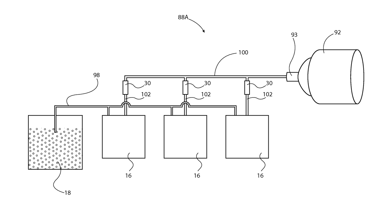
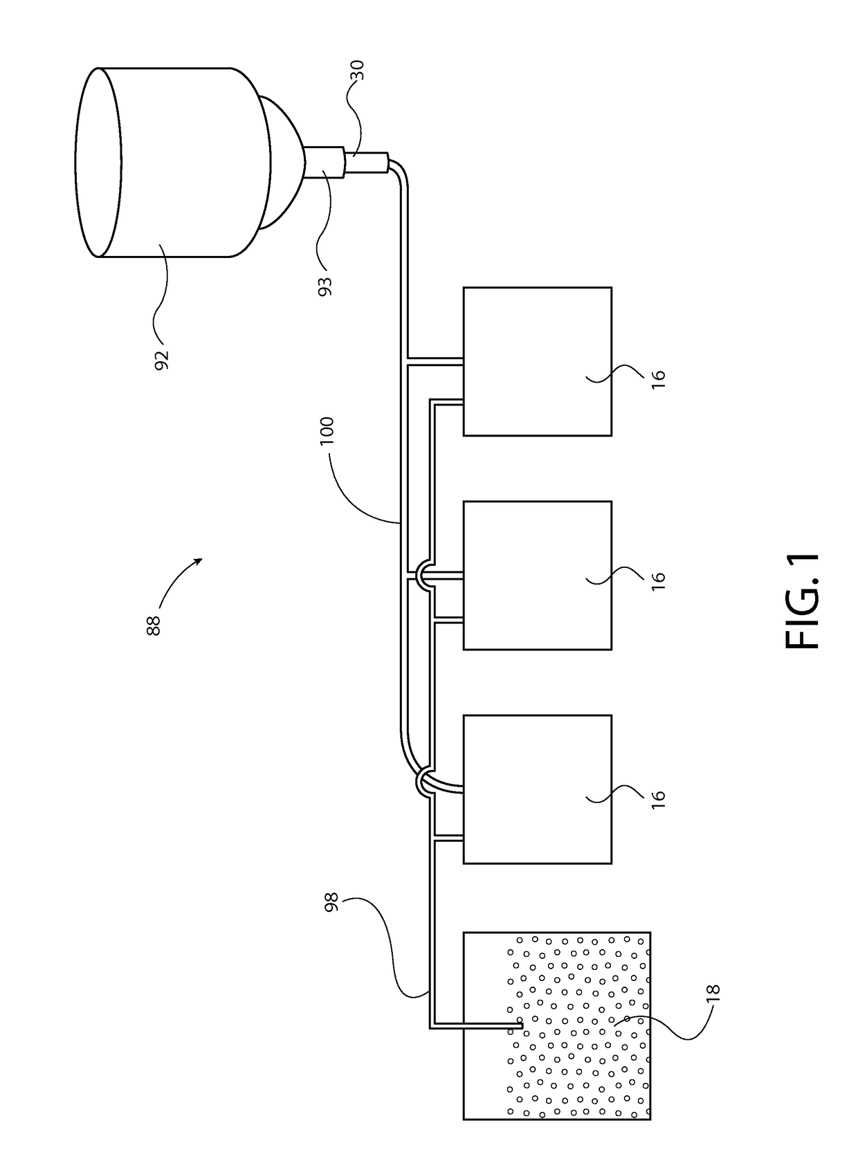
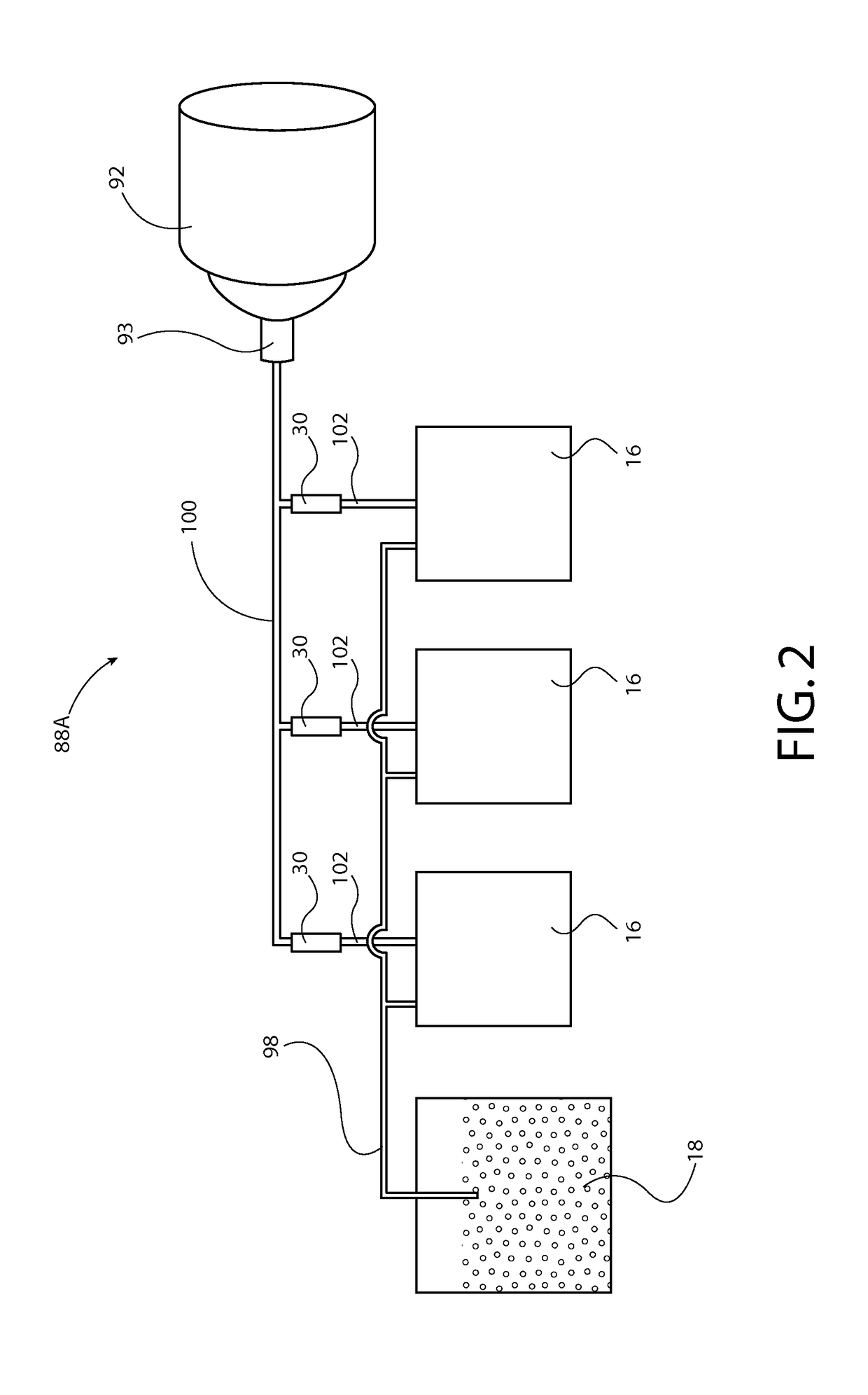
[0071]In this application, unless otherwise apparent from the context it is to be understood that the use of the term “vacuum” means “air at slightly below atmospheric pressure.” The vacuum (meaning air slightly below atmospheric pressure) provides a suction effect that is used to draw granular plastic resin material out of a supply and to convey that granular plastic resin material through various conduits to receivers where the granular resin material can be temporarily stored before being molded or extruded. Hence, in this application it is useful for the reader mentally to equate the term “vacuum” with the term “suction”.

[0072]Referring to the drawings in general and to FIG. 1 in particular, apparatus for conveying granular plastic resin material from the supply to receivers that retain and dispense the resin material when needed by a process machine is illustrated in FIG. 1. The apparatus, which is designated generally 88 in FIG. 1, preferably includes a vacuum pump designated ...


PUM


Abstract

Apparatus and methods for conveying granular plastic resin from a supply to receivers that retain and dispense the resin when needed by process machine include a vacuum pump, an air flow limiter connected to the suction head of the vacuum pump, a first conduit connecting the receivers to the air flow limiter, and a second conduit connecting the resin supply to the receivers.

Description

CROSS-REFERENCE TO RELATED PATENT APPLICATION[0001]This patent application is a 35 USC 120 continuation-in-part of U.S. Ser. No. 14 / 185,016 entitled “Air Flow Regulator” filed 20 Feb. 2014 in the name of Stephen B. Maguire, the priority of which is claimed under 35 USC 120. The disclosure of the '016 application is hereby incorporated in its entirety by reference.BACKGROUND OF THE INVENTION[0002]This invention relates to manufacture of plastic articles and more particularly relates to pneumatic conveyance and processing of plastic resin pellets prior to molding or extrusion of those pellets into a finished or semi-finished plastic product.[0003]In this patent application, injection and compression molding presses and extruders are collectively referred to as “process machines.”BACKGROUND OF THE INVENTION—DESCRIPTION OF THE PRIOR ART[0004]Current resin central loading systems concerned with conveying granular plastic resin pellets from a storage area for molding or extrusion typicall...

Claims


Application Information

Patent Timeline
Patent Type & Authority Patents(United States)
IPC IPC(8): B65G53/24B65G65/36B65G65/32
CPCB65G53/24B65G65/32B65G65/36
Inventor MAGUIRE, STEPHEN B.ZINSKI, JAMES
Owner MAGUIRE PROD
Why Eureka
Try Eureka