Apparatus for automatically lubricating an oil well sucker rod stuffing box

Active Publication Date: 2017-03-28
JAMESON SPECIALTIES INC
View PDF4 Cites 6 Cited by
  • Summary
  • Abstract
  • Description
  • Claims
  • Application Information

AI Technical Summary

Benefits of technology

[0007]The presently disclosed invention is an automated stuffing box lubrication system for oilfield pumping units. The invention provides a precise volume of lubricant to the stuffing box at specified time intervals as selected by the operator. The system comprises a large capacity grease reservoir which supplies grease to the stuffing box by a pump which is activated by a controller. The controller can be programmed to provide a precise volume of grease on a periodic basis. The grease is injected into the stuffing box through a high pressure hose and grease fitting. The controller, pump, pump motor, and grease reser

Problems solved by technology

The movement of the polish rod within the packing material generates friction, and thus heat, which breaks down and degrades the packing materials.
This process reduces the integrity of the seal formed between the packing material and the polish rod.
In further aggravation, the presence of solids in the produced fluid, such as sand, can accelerate this degrading of the packing material as well as adversely impact the life of the polish rod.
The loss of the integrity of the seal between the polish rod and the packing material will resu

Method used


Image

  • Apparatus for automatically lubricating an oil well sucker rod stuffing box
  • Apparatus for automatically lubricating an oil well sucker rod stuffing box
  • Apparatus for automatically lubricating an oil well sucker rod stuffing box

Examples


Embodiment Construction

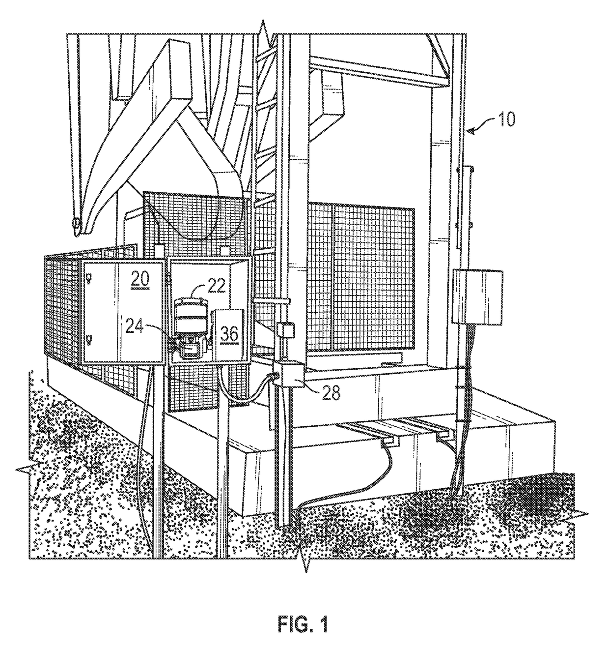
[0018]Referring now to the figures, FIG. 1 shows a known pumping unit 10 which is utilized to impart a reciprocating motion to a rod string. However, as discussed above, embodiments of the invention may also be utilized with pumping systems which utilize rotating rod strings, such as progressive cavity pumps and roto-dynamic pumps. As indicated in FIG. 1, various components of the lubrication system are contained within a weatherproof enclosure 20 which is located at close proximity to the pumping unit 10.

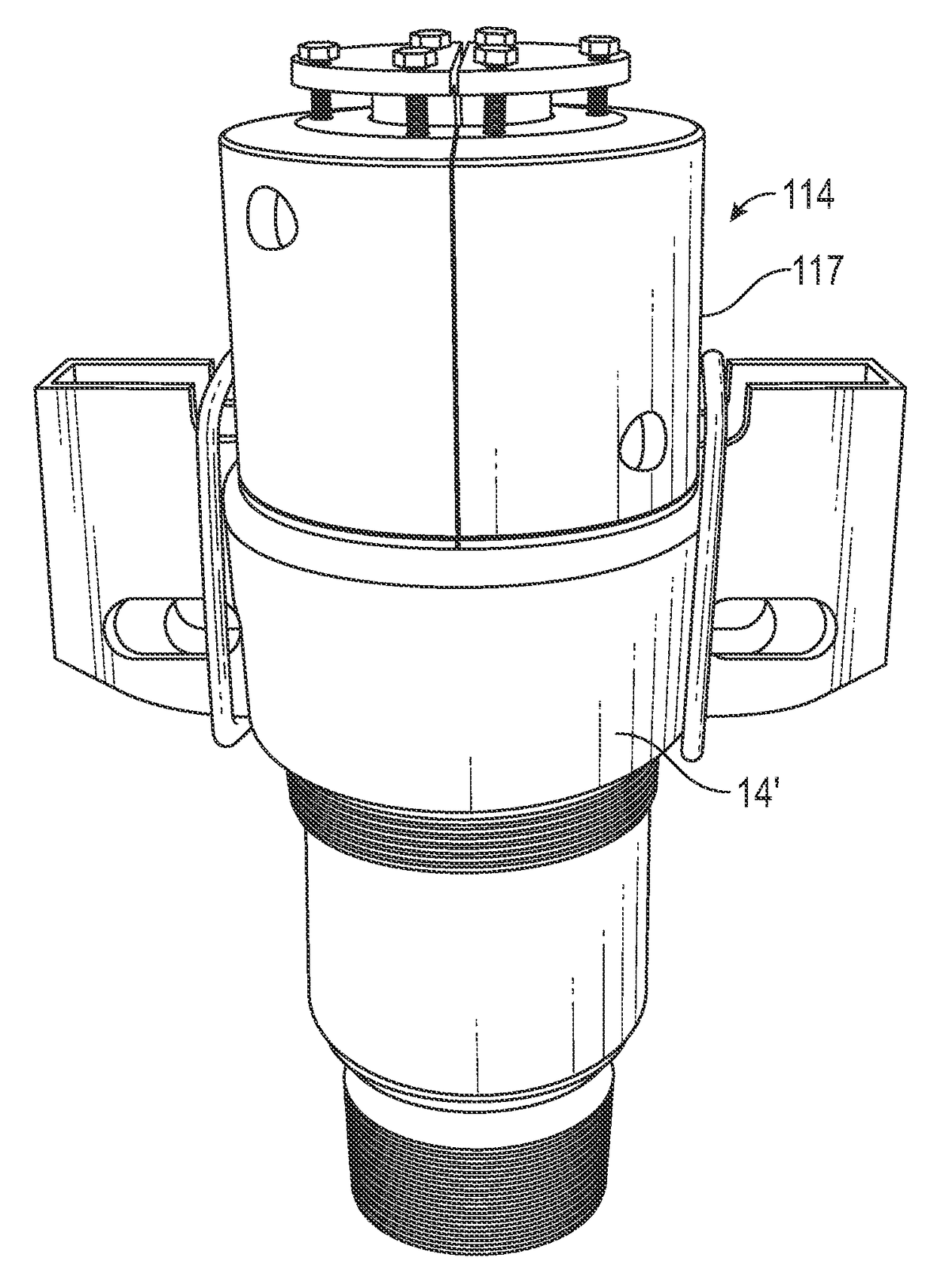
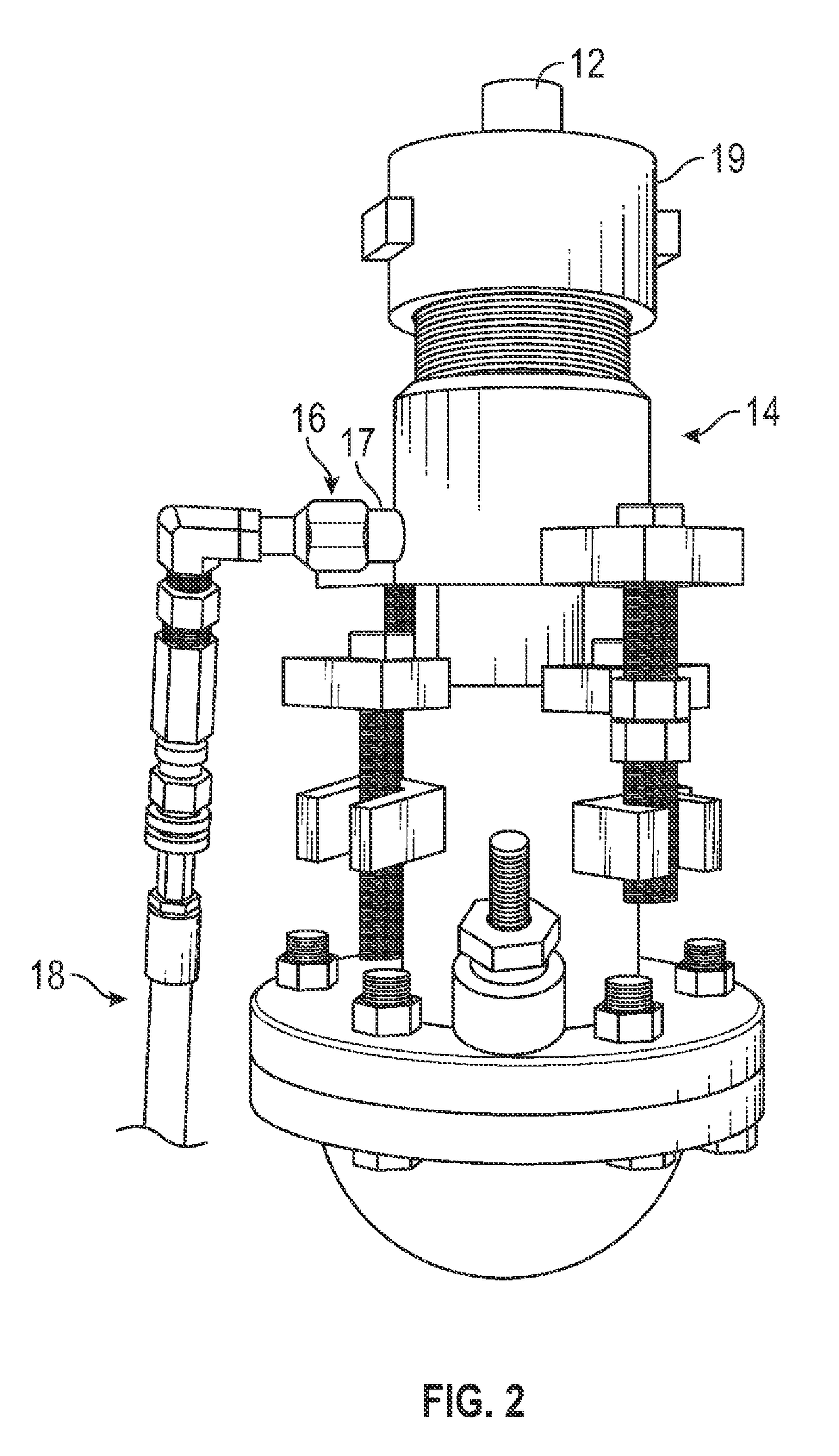
[0019]As shown in FIG. 2, the rod string terminates at the surface with a polish rod 12. Polish rod 12 reciprocates or rotates within stuffing box 14 which contains seal packing elements from maintaining a pressure seal around the polish rod 12. In the present invention, a grease fitting 16 provides access into a cavity containing the packing elements inside the stuffing box 14. A high pressure hose 18 conveys grease from the grease reservoir of the present invention through grease...


PUM


Abstract

A stuffing box lubrication system for oilfield pumping units automatically delivers to the stuffing box, at specified time intervals, a precise volume of lubricant. The stuffing box lubrication system has a grease reservoir, a pump, a controller, a high pressure hose and grease fitting, and a stuffing box which receives the grease. In situations where the stuffing box in use is not equipped with a ported inlet for receiving the grease, the present invention may further include a stuffing box adapter, having a ported inlet, where the stuffing box adapter couples with the stuffing box.

Description

CROSS-REFERENCE TO RELATED APPLICATIONS[0001]This is a non-provisional application which claims priority to provisional patent application No. 61 / 892,337 filed on Oct. 17, 2013.BACKGROUND OF THE INVENTION[0002]The present invention generally relates to artificial lift systems which are utilized for production of fluids from subsurface reservoirs, including oil, water, and liquid phase hydrocarbons. More particularly, the present invention is utilized with artificial lift systems where a subsurface pump is actuated by a plurality of rods connected end-to-end, herein collectively referred to as a “rod string.” The rod string is set within a plurality of tubing joints likewise connected end-to-end, wherein the tubing joints are collectively referred to as a “tubing string.” Actuation of the subsurface pump lifts the fluid upwardly from the subsurface pump to the surface, where the fluids flow in the annular space between the rod string and the inside diameter of the tubing string as th...

Claims


Application Information

Patent Timeline
IPC IPC(8): E21B33/08E21B33/072F16J15/18E21B43/00E21B17/10E21B44/00E21B33/02
CPCE21B33/08F16J15/182F16J15/18E21B33/072E21B44/00E21B17/1071E21B33/02E21B43/00F16N19/006F16N29/04
Inventor JAMESON, WILLIAMUTT, RYAN
Owner JAMESON SPECIALTIES INC
Why Eureka
Try Eureka