
Dynamic current source for zero-crossing amplifier units for use in high-speed communication circuits

a technology of dynamic current source and amplifier unit, which is applied in the direction of physical parameter compensation/prevention, amplification control details, instruments, etc., can solve the problems of non-linearity of high-input/low-out voltage, application which requires sampling rates of more than 1 gs/s, and high sampling ra

Active Publication Date: 2017-03-28
INT BUSINESS MASCH CORP
View PDF8 Cites 1 Cited by
  • Summary
  • Abstract
  • Description
  • Claims
  • Application Information

AI Technical Summary

Benefits of technology

[0008]Moreover, the gain stage may be controlled to provide the gain stage output signal with the initial slope at an initial time and with the end slope when the voltage at the input node passes the threshold voltage due to the coupling with the output node; wherein the slope control means at least increases the duration of the rise and / or fall time of the initial slope.
[0011]It may be provided that the slope control means may be included in the gain stage to increase the duration of a rise and / or fall time of at least one slope of the gain stage output signal output by the gain stage.
[0013]According to an embodiment of a further aspect a method for operating a zero-crossing amplifier unit for use in high speed analog-digital-converters is provided. The method comprises the steps of: comparing a sampling voltage at an input node with a provided threshold voltage to obtain a gain stage output signal; providing a load current depending on a time window between an initial slope and an end slope of the gain stage output signal so that a load capacitance at an output node is loaded by the load current; and increasing a duration of a rise and / or fall time of at least one of the initial and end slopes of the gain stage output signal.

Problems solved by technology

In particular, applications which require sampling rates of more than 1 GS / s require very fast operating gain stages.
In high-speed applications, a delayed turn-on of the current source could result in the time to turn off the current source via the gain stage being not sufficient, thereby causing a non-linearity for high-input / low-output voltages.

Method used


Image

  • Dynamic current source for zero-crossing amplifier units for use in high-speed communication circuits
  • Dynamic current source for zero-crossing amplifier units for use in high-speed communication circuits
  • Dynamic current source for zero-crossing amplifier units for use in high-speed communication circuits

Examples


Embodiment Construction

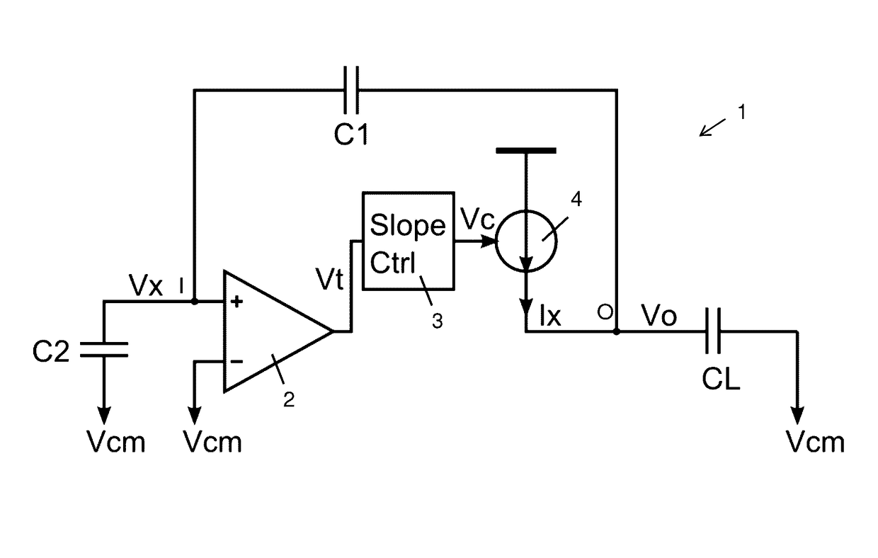
[0020]The zero-crossing amplifier unit 1 as shown in FIG. 1 substantially comprises a gain stage 2 with an inverting and non-inverting input. The gain stage 2 is configured to perform a comparison between the input voltages applied to its inputs. The inverting input of the gain stage 2 is coupled to a provided common mode voltage Vcm as a given threshold voltage. A sampling voltage Vx externally supplied via an input node I is provided to the non-inverting input of the gain stage 2.

[0021]The gain stage 2 is configured to perform an amplification of the input voltage difference with a predetermined gain. Substantially, when the sign of the difference of the input voltages, i.e. sampling voltage Vx and the common mode voltage Vcm (or any other fixed voltage reference), at the inputs of the gain stage 2 changes, a relatively high gradient slope between the supply potentials of the gain stage 2, i.e. VDD and VGND, is provided at its output.

[0022]The output of the gain stage 2 provides a...


PUM


Abstract

A zero-crossing amplifier unit for use in high speed analog-digital-converters. A gain stage compares a sampling voltage at an input node with a provided threshold voltage to obtain a gain stage output signal. A voltage controlled current source provides a load current depending on a time window between an initial slope and an end slope of the gain stage output signal. A slope control means increases a duration of a rise and / or fall time of at least one of the initial and end slopes of the gain stage output signal.

Description

CROSS-REFERENCE TO RELATED APPLICATIONS[0001]This application claims the benefit of priority of United Kingdom Patent Application Serial Number 1301665.4, filed Jan. 31, 2013, which is hereby incorporated by reference in its entiretyFIELD OF THE INVENTION[0002]The present invention relates to zero-crossing amplifier units for high-speed communication circuits, in particular for high-speed analog-to-digital converters.BACKGROUND OF THE INVENTION[0003]Analog-to-digital converters can be implemented with different topologies. In particular, interleaved and pipelined analog-to-digital converters require gain stages which need to be operable at very high-speed. The main requirements for these gain stages are to obtain a gain of more than 1 in a short time while preserving linearity.[0004]Among the broad variety of ADC topologies, ADCs with zero-crossing amplifier units have recently gained attention for use in high-speed high-resolution applications. In particular, applications which req...

Claims


Application Information

Patent Timeline
Patent Type & Authority Patents(United States)
IPC IPC(8): H03G3/30H03M1/06H03G1/00H03M1/50
CPCH03G3/3042H03G1/0029H03M1/0607H03G1/0005H03G3/3005H03M1/50
Inventor KULL, LUKASTOIFL, THOMAS
Owner INT BUSINESS MASCH CORP
Learn More