Image forming apparatus, image forming method, program, and ophthalmic apparatus

a technology of image forming and forming methods, applied in the field of image forming apparatuses and methods, can solve problems such as disadvantageous distortion of formed images, and achieve the effect of reducing distortion of images

Active Publication Date: 2017-04-11
CANON KK
View PDF14 Cites 0 Cited by
  • Summary
  • Abstract
  • Description
  • Claims
  • Application Information

AI Technical Summary

Benefits of technology

[0006]In view of the problem described above, the present invention is to reduce a distortion in an image, which occurs when the image is formed by scanning a retina with a resonance scanner.
[0009]According to the present invention, based on the correlation between the signal groups relating to the resonance scanner, which are detected for each cycle of the first frequency set for the resonance scanner, the second frequency, which is estimated as having been (actually) used for the scanning by the resonance scanner, can be determined. In this manner, the distortion of the image, which occurs when the image is formed by scanning the retina with the resonance scanner, can be reduced.

Problems solved by technology

As a result, a distortion disadvantageously occurs in the formed image.

Method used


Image

  • Image forming apparatus, image forming method, program, and ophthalmic apparatus
  • Image forming apparatus, image forming method, program, and ophthalmic apparatus
  • Image forming apparatus, image forming method, program, and ophthalmic apparatus

Examples


first embodiment

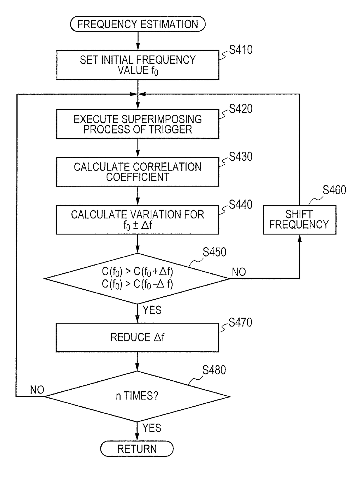
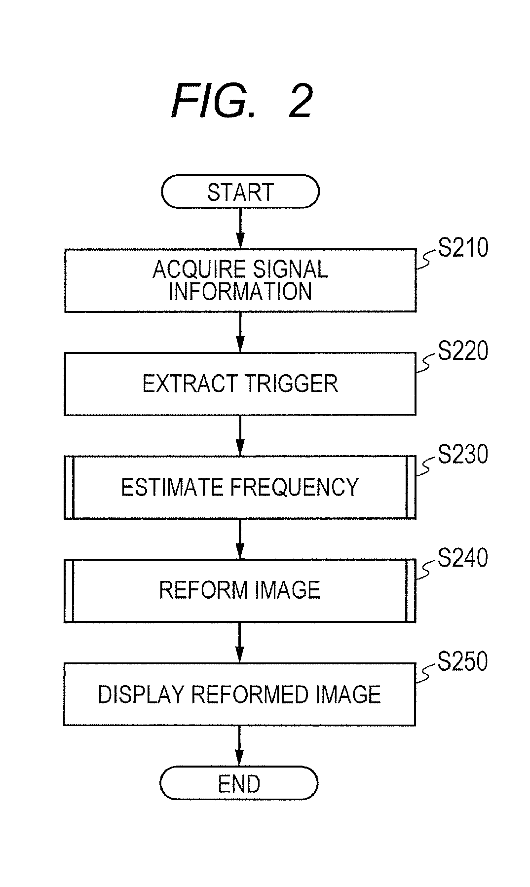
[0023]In a first embodiment of the present invention, there is described processing for reforming an image based on signal values obtained by the combination of a resonance scanner and a galvano scanner when an image of a retina photographed by an adaptive optics SLO is to be acquired. Specifically, a group of trigger signals for the galvano scanner (hereinafter referred to as “galvano triggers”), which corresponds to one image, and a group of trigger signals for the resonance scanner (hereinafter referred to as “resonance triggers”), which corresponds to two vertical reciprocation lines of the image, are acquired. By using the trigger signals, a frequency of the resonance scanner for the one image is estimated as a frequency which minimizes a variation between positions at which the trigger signals for the resonance scanner are acquired. Based on the estimated frequency, a correction for a reform start position and a sine correction are performed to reform the image. By reforming t...

second embodiment

[0101]In the first embodiment, there has been described the processing of evaluating the estimate value of the frequency of the resonance scanner by using the correlation coefficient and acquiring the frequency at which the correlation coefficient becomes the largest as the estimate value, to automatically reform the image.

[0102]According to a second embodiment of the present invention, the value of the frequency is changed while a user is observing the image.

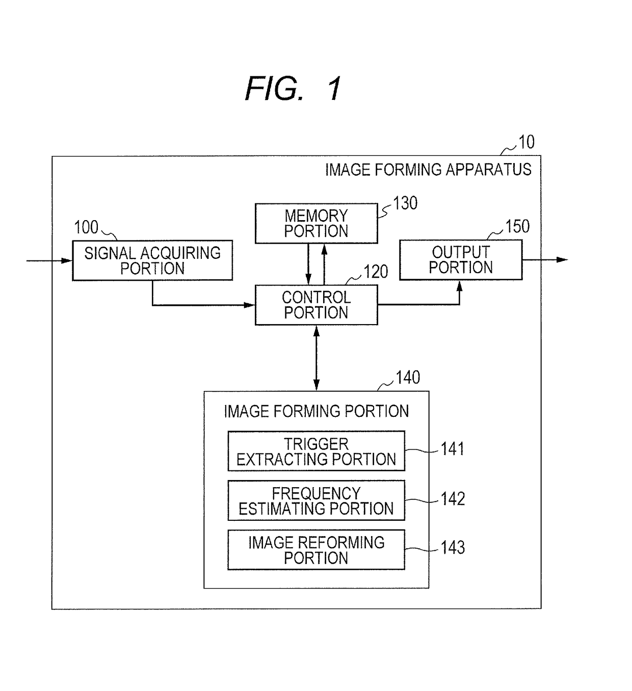
[0103]A functional configuration of the image forming apparatus 10 according to the second embodiment is illustrated in FIG. 11. The functional configurations of the signal acquiring portion 100, the control portion 120, the memory portion 130, and the output portion 150 are the same as those illustrated in FIG. 1, and therefore the description thereof is herein omitted. In the second embodiment, the image forming portion 140 includes only the trigger extracting portion 141 and the image reforming portion 143. Instead of the es...


PUM


Abstract

A distortion in an image, which occurs when the image is formed by scanning a retina with a resonance scanner, is reduced. An image forming apparatus for forming an image of an object to be inspected includes: a detecting unit for detecting signals relating to a resonance scanner which is set to scan the object to be inspected with measurement light at a first frequency; a determining unit for determining a second frequency which is estimated to be used for the scanning by the resonance scanner, based on a correlation between groups of the detected signals for each cycle of the first frequency; and an image forming unit for forming the image of the object to be inspected based on the determined second frequency.

Description

BACKGROUND OF THE INVENTION[0001]Field of the Invention[0002]The present invention relates to an image forming apparatus and method, and more particularly, to an image forming apparatus and method used for an ophthalmic care and the like, a program, and an ophthalmic apparatus.[0003]Description of the Related Art[0004]An examination of a fundus of an eye is widely performed for the purpose of a diagnosis in early stage of a disease that usually ranks high in adult disease or cause of blindness. A scanning laser ophthalmoscope (SLO) which uses a principle of a confocal laser microscope is an ophthalmic apparatus that performs a raster scanning on a fundus of an eye with laser light which is measurement light and acquires a two-dimensional image of the fundus of the eye from return light with a high resolution at a high speed. In recent years, an adaptive optics SLO has been developed which includes an adaptive optical system for measuring an aberration of an eye to be inspected in re...

Claims


Application Information

Patent Timeline
Patent Type & Authority Patents(United States)
IPC IPC(8): A61B3/14A61B3/10
CPCA61B3/1025A61B3/14
Inventor YONEZAWA, KEIKO
Owner CANON KK
Why Eureka
Try Eureka