Light emission structure for indication symbol in interior space of vehicle

a technology of indication symbols, which is applied in the direction of fluorescence/phosphorescence, instruments, transportation and packaging, etc., can solve the problems of increasing the number of light sources and components, increasing the complexity of wiring connections, and difficulty in readily providing additional light-emitting or luminescent symbols, so as to avoid discomfort for drivers and passengers. , the effect of easy addition

Active Publication Date: 2017-04-11
YAZAKI CORP
View PDF37 Cites 81 Cited by
  • Summary
  • Abstract
  • Description
  • Claims
  • Application Information

AI Technical Summary

Benefits of technology

[0015]Another advantageous effect of the present invention is that a luminescent symbol of the additionally provided functional unit can become luminous simply by providing the functional unit such that it resides within the irradiation area to be irradiated by the ultraviolet light source, which allows the luminescent symbols to be readily added.
[0016]Also, since the functional units are provided within the irradiation area irradiated by the ultraviolet light from the ceiling part, i.e., within the range viewable from the ceiling part, it is possible to prevent an obstacle from intervening the irradiation of the ultraviolet light upon the functional unit.
[0017]Further, since the luminescent symbol becomes luminous when being irradiated by the ultraviolet light, it does not emit light with a high brightness that a driver or a passenger may feel it too bright, so that discomfort of the driver and the passenger can be avoided.
[0018]Yet another advantageous effect is that since the ultraviolet light is emitted from the ceiling part, it is possible to prevent the ultraviolet light from being emitted directly upon the eyes of the driver or the passenger.
[0020]With this configuration, it is possible to uniformly control the brightness of the luminescent symbols of the functional units provided in the automotive or vehicular interior space, and accordingly it is not necessary to individually control the brightness of the luminescent symbols on a per-functional unit basis, which significantly facilitates the brightness control.

Problems solved by technology

Since the above-described meter device and the various types of on-board devices are independently provided and spaced from each other, it is necessary to individually provide the light sources on a per-on-board-device basis for light emission or luminescence of the individually-provided indication symbols, which necessarily increases the number of components, complexity of wiring connections, and the manufacturing costs.
In such cases that involve design changes that necessitates incorporation of additional light-emitting or luminescent symbols for increasing the operability and aesthetic appearance of the various types of devices provided in the automotive interior space, a larger number of light sources may have to be provided, which further increases the number of light sources and the components and the complexity of the wiring connections, which further makes it difficult to readily provide the additional light-emitting or luminescent symbols.

Method used


Image

  • Light emission structure for indication symbol in interior space of vehicle
  • Light emission structure for indication symbol in interior space of vehicle
  • Light emission structure for indication symbol in interior space of vehicle

Examples


Embodiment Construction

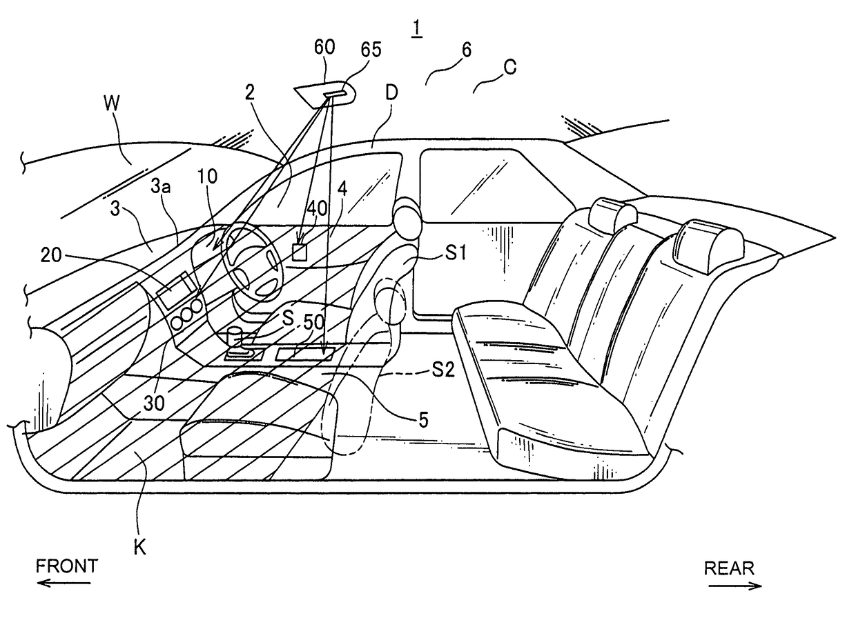
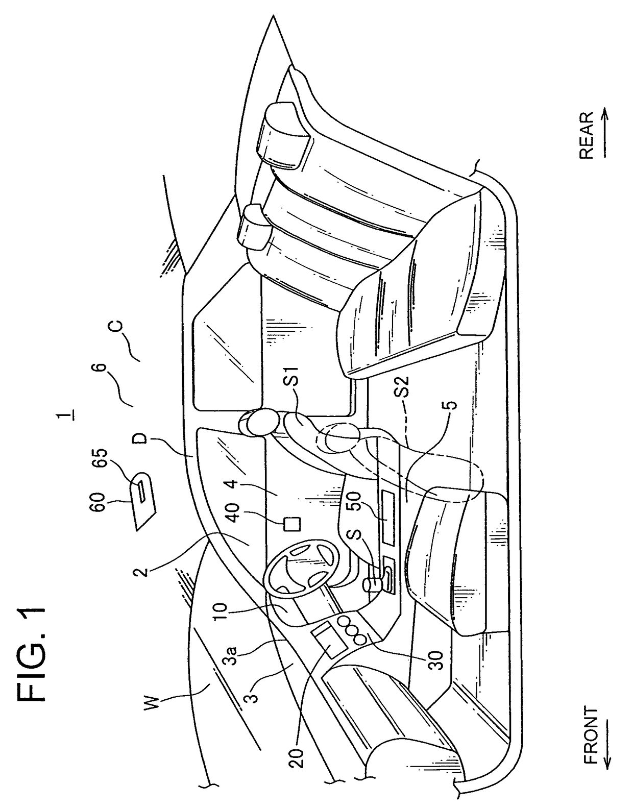
[0035]With reference made to FIGS. 1 through to 12, the following describes an interior of an automobile with a light emission structure (or luminescence structure) for an indication symbol according to one embodiment of the present invention, the indication symbol being provided in the interior space of the automobile.

[0036]Referring to FIG. 1, there are shown an automotive interior space 2 in an automobile 1 (which is a “vehicle” in the context of the scope of the invention).

[0037]A driver-side door D includes a door interior panel 4 on its surface defining the interior space 2. Other doors of the automobile 1 may each include a door interior panel of the same or similar configuration.

[0038]A roof interior panel 6 is provided on a surface of a ceiling C defining the interior space 2.

[0039]An instrument panel 3 and a center console 5 are provided in the interior space 2.

[0040]The instrument panel 3 is arranged in a space below a windshield glass W provided in a front side of the au...


PUM


Abstract

An interior space of an automobile includes a maplamp unit and a plurality of functional units. The maplamp unit is provided on a ceiling of the interior space and is adapted to emit an ultraviolet light therefrom toward and upon a predetermined area of irradiation by the ultraviolet light. The functional units are spaced from each other and yet provided such that they all reside within the irradiation area. The functional units may include a combination meter, a navigation device, an air conditioner operating area, a power window switch area, and a small article placing area. These functional units each include at least one luminescent symbol. The luminescent symbol is adapted to become luminous when irradiated by the ultraviolet light emitted by the maplamp unit.

Description

CROSS-REFERENCE TO RELATED APPLICATION[0001]This application claims priority to the Japanese Patent Application No. 2010-016335 filed on Jan. 28, 2010, the disclosure of which is incorporated herein by reference in its entirety.BACKGROUND OF THE INVENTION[0002]1. Field of the Invention[0003]The present invention relates to a light emission or luminescence structure for an indication symbol provided in an interior space of an automobile or other vehicle.[0004]2. Background Art[0005]Conventional meter devices such as a speedometer incorporated in an instrument panel of an automobile or other vehicle include (a) a dial having a light-transmissive indication symbol such as numerical values, scale marks and any other iconographic symbols or signs and (b) a light source adapted to illuminate the dial from a back side thereof.[0006]In the conventional meter devices of this kind, a light is emitted from the light source toward the dial in response to turning on of the automobile's headlight...

Claims


Application Information

Patent Timeline
Patent Type & Authority Patents(United States)
IPC IPC(8): B60Q3/00
CPCB60Q3/18B60Q3/12B60Q3/68
Inventor SAWAYANAGI, MASAHIRO
Owner YAZAKI CORP
Why Eureka
Try Eureka