
Conveyor belt and drive belt comprising knitted belt, and conveyor device using conveyor belt

a technology of conveyor belts and drive belts, which is applied in the direction of driving belts, belts/chains/gearings, thin material processing, etc., can solve the problems of increasing manufacturing costs, affecting the quality of knitted belts, so as to reduce the elongation of the belt, and the effect of not easily deformed

Active Publication Date: 2017-04-11
SANWA TECHNO CO LTD +1
View PDF18 Cites 11 Cited by
  • Summary
  • Abstract
  • Description
  • Claims
  • Application Information

AI Technical Summary

Benefits of technology

The solution effectively prevents fraying, improves belt strength and tension, and enhances gripping characteristics, allowing stable conveyance of lightweight objects without air suction, reducing manufacturing costs and energy consumption.

Problems solved by technology

In the context of conventional woven belts comprising woven fabric or conventional knit belts comprising knit fabric, where these are formed such that the entirety is of mesh construction, there has been occurrence of fraying of yarn at belt side ends or at locations where the belt is rubbed.
However, when such an endless belt comprising woven fabric or knit fabric has been driven, it is sometimes the case that the endless belt undergoes lateral displacement and meanders.
However, steps comprising projections and recesses which are parallel to the direction of travel and which might serve as guides with respect to the direction of travel have typically not been provided at the belt itself.
However, there has been the problem that employment of secondary processing for provision of such guides has resulted in increased manufacturing cost.
Furthermore, the strength of a mesh belt, i.e., a belt which is such that the entire surface of the belt which comprises woven fabric or knit fabric is made of mesh, cannot ordinarily be described as adequate.
However, where such rubber-coated belts have been employed, it has been necessary to carry out processing so that the belt could be provided with holes at rubber-coated portions so as not to defeat the purpose of the underlying mesh, which has increased cost.
Thus, rubber-coated laminated belts comprising rubber elastic bodies and woven fabric or knit fabric (hereinafter these are referred to collectively as “woven / knit fabric”) are expensive.
Because knit fabric is typically of high flexibility, belts made up of only knit fabric are almost never found.
Furthermore, because belts comprising knit fabric have high flexibility, preventing attainment of sufficient belt tension, and because the coefficient of friction of the belt is moreover low, causing the gripping force produced by the force of friction to be inadequate, it is necessary to apply a rubber coating or the like to the surface of the belt as described above so that an adequate gripping force due to the force of friction can be obtained.
Moreover, with conventional belts comprising woven / knit fabric, there have been problems such as the fact that there is fraying of yarn at belt side ends, or there is breakage of yarn where the belt is rubbed, and that this causes a run in the material from that point, as a result of which the belt is immediately made unfit in use.
Moreover, in the context of a method for manufacturing stockinette hosiery, a technique has been proposed in which heat sufficient to cause fusing of hot-melt yarn but insufficient to cause melting of heat-shrink yarn is applied to knitted cloth comprising such yarns so as to cause the knitted cloth to shrink and so as to also cause adhesion at the hot-melt yarn to prevent fraying of stitches (see, for example, Patent Reference No. 11).

Method used

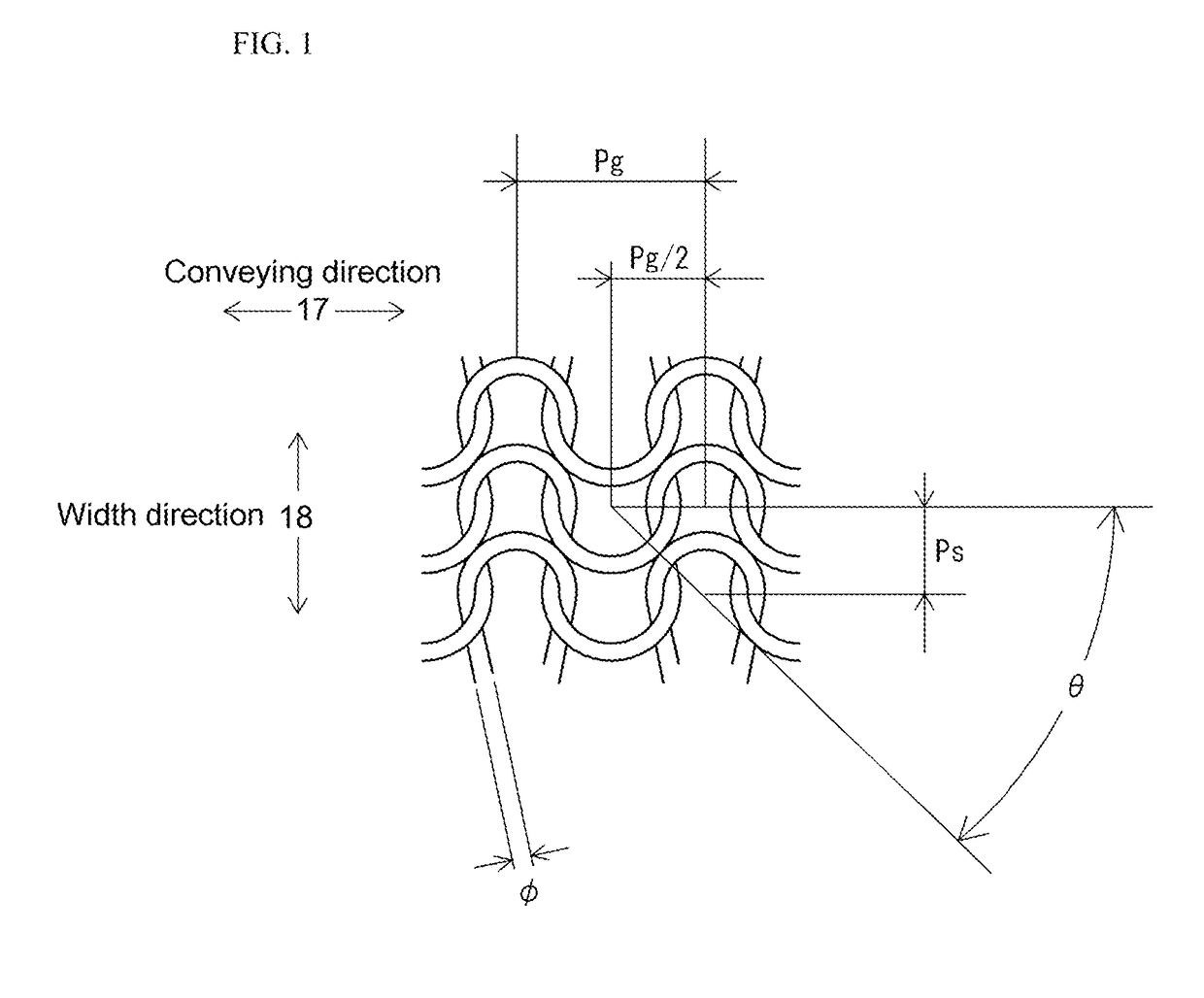
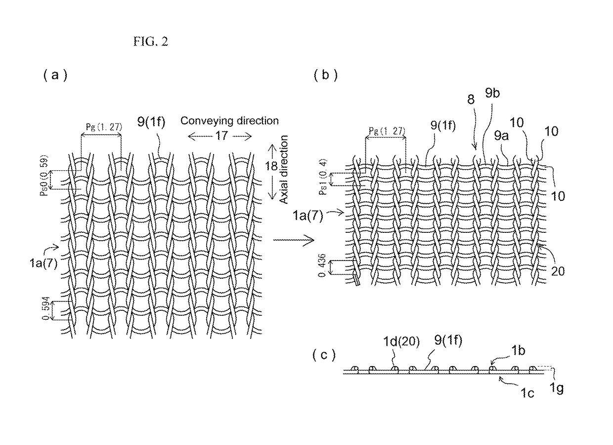

Image

  • Conveyor belt and drive belt comprising knitted belt, and conveyor device using conveyor belt
  • Conveyor belt and drive belt comprising knitted belt, and conveyor device using conveyor belt
  • Conveyor belt and drive belt comprising knitted belt, and conveyor device using conveyor belt

Examples


working examples

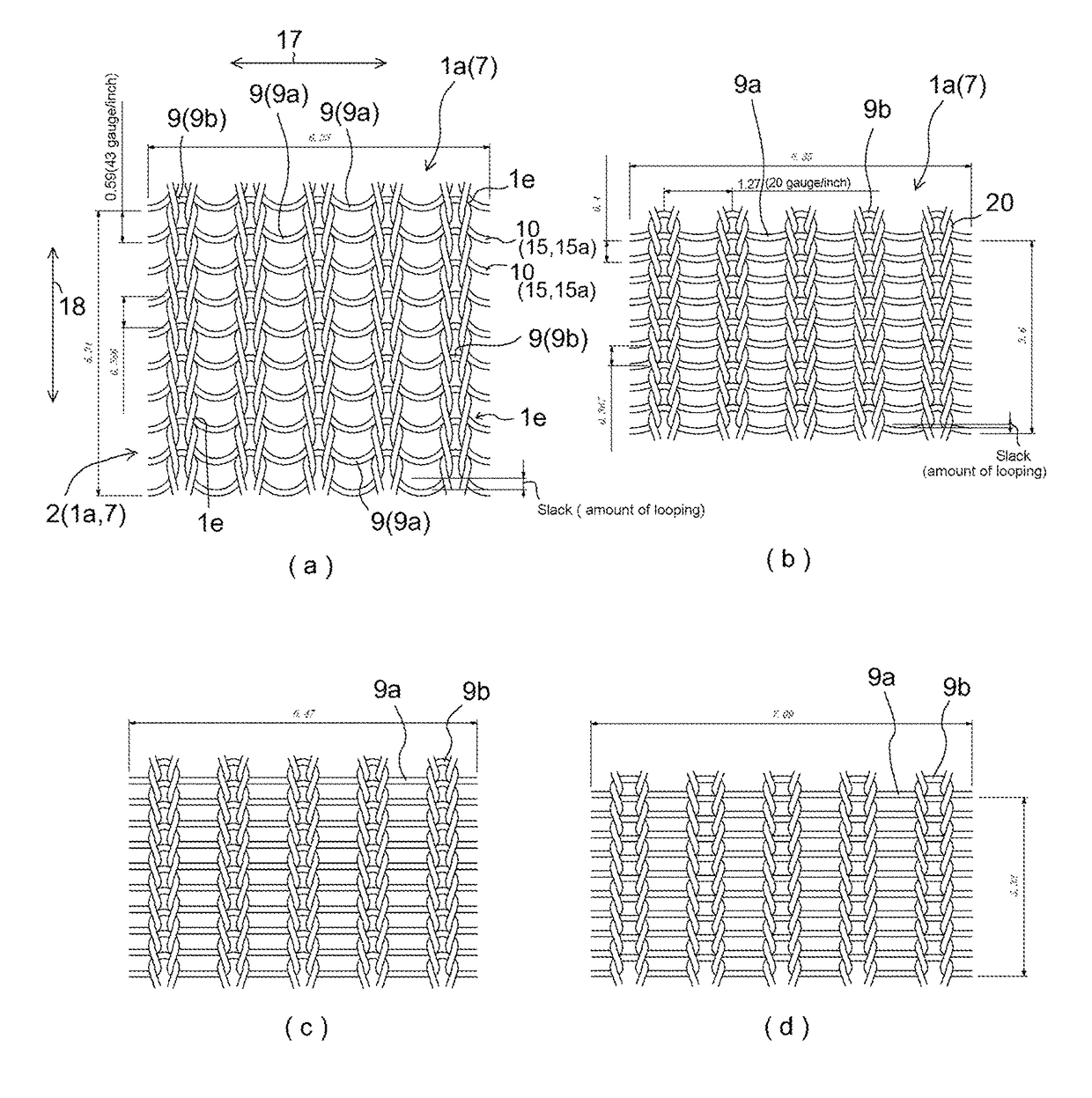
[0099]TABLE 1 lists filament material, whether heat-setting was carried out, and various other characteristics of Working Examples 1 through 6, which are knit belts 1a comprising knit fabric 7 which is weft-knit 7a associated with the present invention, and Comparative Example 1, which is a mesh belt comprising woven fabric made in plain weave for purposes of comparison therewith. At this TABLE 1, Working Examples 1 through 4 were such that a seamless knit belt 4, as is for example shown in FIG. 8, comprising knitting in which, to increase coefficient of friction, urethane filament elastic fiber comprising modified cross-section as shown at (h) in FIG. 11 was used as plating yarn 12a of modified cross-section to carry out plating of a core yarn 11 which was Nylon (trade name) filament. Working Example 5 indicates a seamless knit belt 4 constituted of only monofilament 15a. Moreover, Working Example 6 indicates a seamless knit belt 4 that was formed such that Nylon (trade name) filam...


PUM


Abstract

(PROBLEM) To provide a seamless conveyor belt comprising knit fabric.(SOLUTION MEANS) A seamless conveyor belt employing monofilament made up of continuous fiber at filament constituting core yarn; being made up of weft-knit or warp-knit in which there is mutual intertwining of filament; flexural stress and heat causing monofilament at core yarn to undergo plastic deformation at locations of entanglement; being a seamless knit belt (1a) comprising a knit pattern (8) which is weft-knit or warp-knit; being a knit pattern (8) in which pitch (Ps) of stitch loops in a width direction (18) is smaller than pitch (Pg) of stitch loops in a conveying direction (17) of the seamless knit belt; mutually contacting loops (9) and filament undergoing deformation; entangled regions of filament being maintained; fraying at side ends of the knit belt (1a) during conveyance by the conveyor belt being prevented; spacing of pitch (Ps) of stitch loops in the width direction (18) being small; and strength being improved.

Description

TECHNICAL FIELD[0001]This invention relates to a drive belt that transmits drive force or a conveyor belt that conveys a lightweight sheet-like object, lightweight pill, or granule-like object. It is generally the case, during use of a conveyor belt to convey at high speed any of a variety of medicinal pills or any of various other such small objects or any of a variety of separate sheets of sheet-like papers, that the paper or small object, being lightweight, is while being conveyed apt to float, which can prevent it from being conveyed in its proper orientation. The present invention therefore relates to a drive belt which drives at high speed or to a conveyor belt that has a structure such as will, when conveying such lightweight and / or small objects at high speed, prevent such small objects from floating above the conveyor belt and allow them to be conveyed in their proper orientations, or has a structure such as will allow conveyed objects to be sandwiched as they are conveyed,...

Claims


Application Information

Patent Timeline
Patent Type & Authority Patents(United States)
IPC IPC(8): B65G15/54F16G1/04B65H5/02
CPCB65G15/54B65H5/02F16G1/04B65H2404/271
Inventor SHOJI, SUSUMUFUKUI, KAZUROKURAHASHI, TAKAOMIIIDA, MASATO
Owner SANWA TECHNO CO LTD
Learn More