Centrifugal gas compressor method and system

a gas compressor and centrifugal technology, applied in the direction of liquid fuel engines, liquid degasification, separation processes, etc., can solve the problems of poor efficiency of prior art commercial gas compressors, inability to dissipate the heat of compression during the compression process, and inability to achieve the effect of retaining heat in gas

Active Publication Date: 2017-04-11
CARNOT COMPRESSION INC
View PDF34 Cites 11 Cited by
  • Summary
  • Abstract
  • Description
  • Claims
  • Application Information

AI Technical Summary

Benefits of technology

[0010]It is an object of the present invention to provide a centrifugal gas compressor and a method for compressing a gas entrained in a liquid or an emulsion or a gas-liquid mixture.
[0011]It is another object of the present invention to provide a centrifugal gas compressor and a method therefor which is essentially isothermal in nature.

Problems solved by technology

The efficiency of prior art commercial gas compressors is poor primarily because practicalities require that the gas be compressed rapidly.
Rapid compression makes it nearly impossible to dissipate the heat of compression during the compression process.
However, most compressed gas is stored in an uninsulated pressure vessel and the time between the compression of the gas and the use of the gas makes retention of the heat in the gas impractical.
Therefore, this 50-100% additional work to compress the gas is lost or wasted.
Historically isothermal compression has been impractical or impossible to achieve because the time for the C-heat to be removed from the walls of the compression device mandates a very slow compression cycle so that heat removal can keep pace with the heat generated by the compression.
However, the Rees '865 rotary pump compressor utilized large cavities having highly curved shaped walls and the cavities were not radial with respect to the rotating container.
However, there are no details of the centrifugal separator.

Method used


Image

  • Centrifugal gas compressor method and system
  • Centrifugal gas compressor method and system
  • Centrifugal gas compressor method and system

Examples


Embodiment Construction

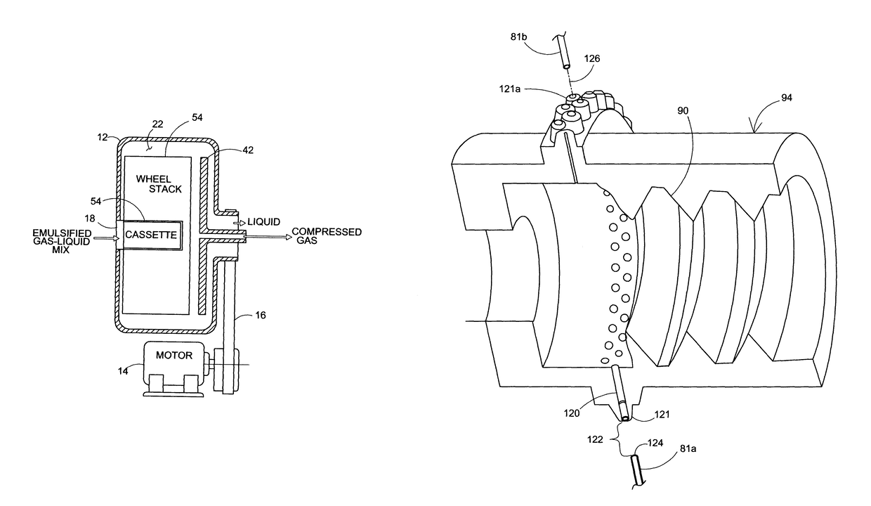
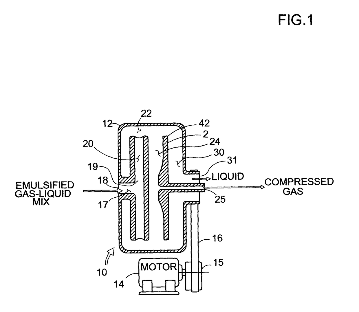
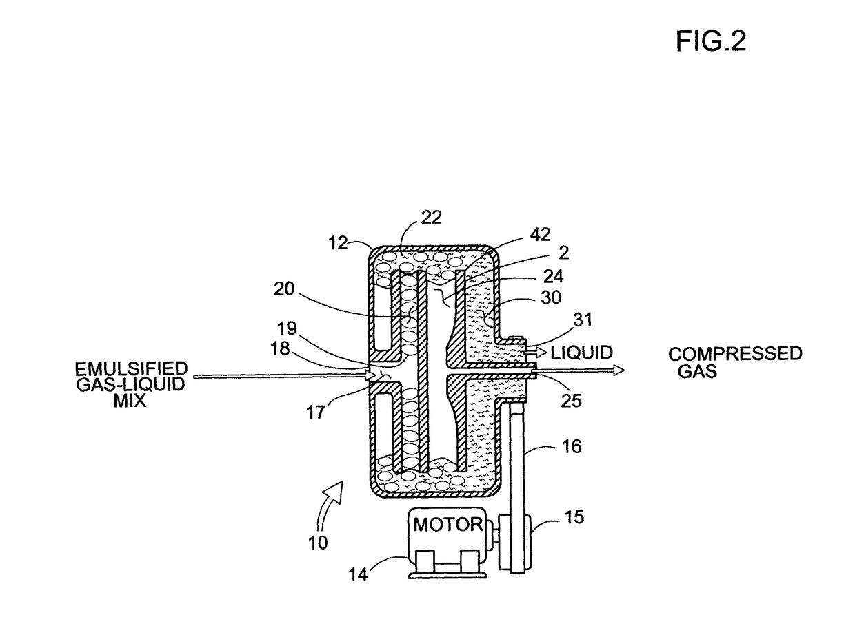
[0034]The present invention relates to a method for compressing a gas entrained in a liquid (such as air entrained in a water, or an emulsified air-liquid mixture, or natural gas (in a gaseous state) entrained in liquified natural gas, among others) in a centrifugal gas compressor. Similar numerals designate similar items throughout the patent specification.

[0035]An ideal compressor would apply force to a spherical surface that reduces in diameter to compress the gas. Unlike a piston or screw compressor, a spherical compressor surface area reduces the sphere by the 3rd power of its radius. A piston's surface area remains constant and therefore requires increasing force to overcome the increasing gas pressure. However, in a spherical compressor, the square inches of spherical surface area (translated to pounds per square inch (PSI)) are reduced by the third root of the volume change. Therefore, a spherical compressor would nearly cancel out the increasing force of the increasing gas ...


PUM

PropertyMeasurementUnit
pressureaaaaaaaaaa
diametersaaaaaaaaaa
inner diametersaaaaaaaaaa

Abstract

The compressor compresses gas in capillaries leading to a radially distant annular container space. Centrifugal force acts on gas bubbles entrained between liquid slugs moving radially outward through the capillaries which may be radial, tangential or continuously curved. Compressed gas is collected in the annular space. A gas-liquid emulsion is fed to the capillaries by an inboard emulsification device. The emulsification may include a vortex generator, an ejector or a venturi injector, all feeding the gas-liquid mixture into the inboard ends of the capillaries. The capillaries are formed in a series of discs, coaxially stacked with outer disc ends open to the annular space. Capillary inlets may be perpendicular, tangential or may define a venturi jet.

Description

[0001]This is a regular patent application based upon and claiming the benefit of provisional patent application Ser. No. 61 / 847,161 filed Jul. 17, 2013, the contents of which is incorporated herein by reference thereto.[0002]The present invention relates to a centrifugal gas compressor, a method for compressing gas using centrifugal forces in a plurality of capillary passages leading radially to an annular collection cavity, and a system for centrifugal gas compression.BACKGROUND OF THE INVENTION[0003]Gas compressors are used for many items in the consumer market (to inflate basketballs, toys and tires) and in the industrial market (to compress gas for transport, for powering pneumatic tools and for distributing natural gas from the well head to the user).[0004]The efficiency of prior art commercial gas compressors is poor primarily because practicalities require that the gas be compressed rapidly. Rapid compression makes it nearly impossible to dissipate the heat of compression du...

Claims


Application Information

Patent Timeline
Patent Type & Authority Patents(United States)
IPC IPC(8): F04F99/00F04D17/16F04D31/00F04D29/70F04D17/18B01D19/00
CPCF04D29/706B01D19/0057F04D17/167F04D17/18F04D31/00F05D2210/132
Inventor CHERRY, MARK A.ALDERMAN, ROBERT A.SHILLINGER, D. HANS
Owner CARNOT COMPRESSION INC
Why Eureka
Try Eureka