Method for manufacturing transparent conductive film

a technology of transparent conductive film and manufacturing method, which is applied in the direction of dielectric characteristics, insulation conductors/cables, instruments, etc., can solve the problems of reducing production efficiency, difficult to ensure the quality of the inlaid circuit on the surface and easy cracks easily occurring on the circuit, so as to achieve quick and evenly filled, improve the quality and uniformity of the large area substrate of the transparent conductive film, and improve the quality of the large area substra

Active Publication Date: 2017-04-11
XI AN JIAOTONG UNIV
View PDF1 Cites 2 Cited by
  • Summary
  • Abstract
  • Description
  • Claims
  • Application Information

AI Technical Summary

Benefits of technology

[0007]In view of the above-described problems, it is one objective of the invention to provide a method for manufacturing a transparent conductive film. The method is based on the principle of electric hydrodynamics, different liquid phase conductive slurry (for example, a liquid phase or a compound of high rheology formed by a mixture of different low dimensional nanomaterials) can be quickly and evenly filled into prefabricated grooves of a micron or even nano scale on a transparent film driven by an electric force and a scrapper. The grooves of the micron or nano scale are made using different commercialize imprint technology. The filling effect of the conductive slurry is not impacted by the shape of the opening, the direction, or the depth of the grooves or the moving direction of the scrapper, so that the production efficiency, the quality and the uniformity of large area substrate of the transparent conductive film are largely improved.
[0016]Advantages of the invention according to embodiments of the invention are as follows: the method of the invention is applicable for a wide range of liquid phase or a conductive slurry having high rheology, including a water suspensions or organic slurries synthesized by a different low-dimensional nanomaterials (such as nano metal particles or nano lines, or carbon nanotubes, or graphene). Based on the principle of electric hydrodynamics, the functional liquid material is filled into the prefabricated groove of the transparent film. Not only is the high filling efficiency realized, but also the defects of the air bubble entrapment or the uneven filling are avoided, thereby improving the quality and the yield of the circuit.

Problems solved by technology

However, fissures easily occur on the circuit or the circuit is easily separated from the surface of the transparent film substrate, particularly in flexible display device.
However, in large area scrapping-filling process, to reduce defects resulting from uneven depth or entrapment of air bubbles, the scrapping is often conducted at low scrapping speed, which reduces the production efficiency and makes it difficult to ensure the quality of the inlaid circuit on the surface of the large area substrate.

Method used


Image

  • Method for manufacturing transparent conductive film
  • Method for manufacturing transparent conductive film
  • Method for manufacturing transparent conductive film

Examples


example 1

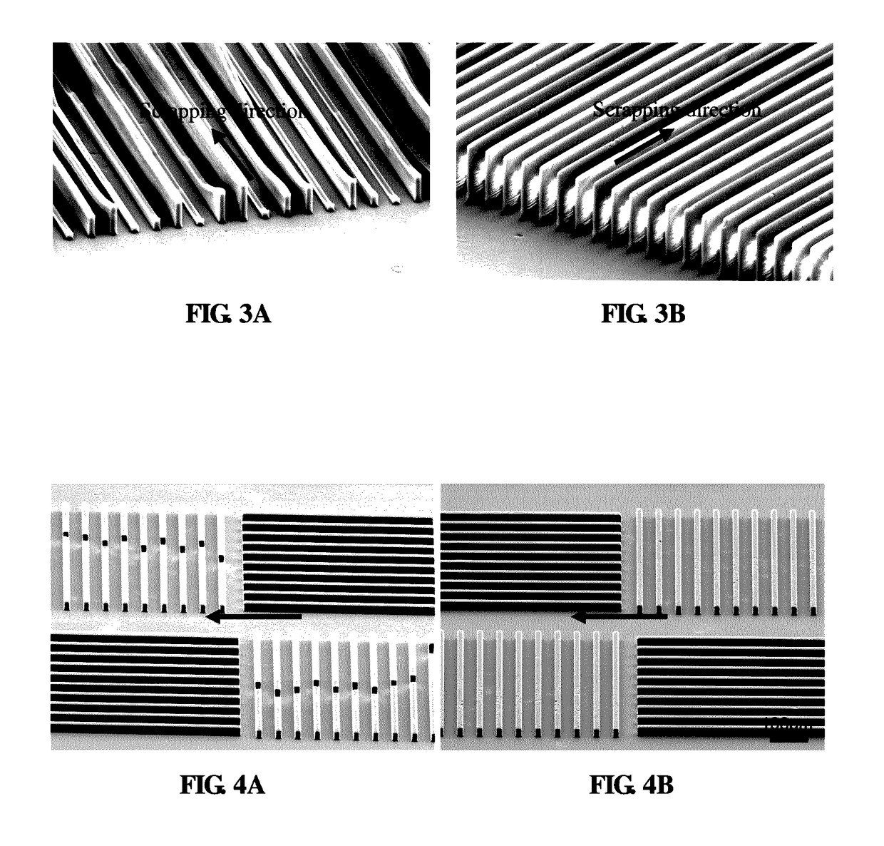
[0031]To illustrate the superiority of the scrapping method adopting the electrodynamic force in the filling efficiency and the filing effect, a UV cured conductive material is used in this example. The UV cured conductive material is filled in the grooves of the transparent film, and a UV light is used to cure the conductive material. The conductive material is then separated from the grooves of the transparent film. The advantage of the filling driven by the external electric filed is evaluated by observation of an integrity of the microstructure of the separated conductive material. Comparisons of the filling efficiencies are made between conventional method and the present method using the external electric field. FIG. 3A is a picture showing a filling effect obtained from the conventional method (in the absence of applying any voltage). FIG. 3B is a picture showing the filling effect obtained from the present method by applying a voltage of 200 V. Both the methods are conducted...

example 2

[0032]Because directions of the grooves of the transparent film are variable in practical operation, filling effects of grooves in different directions are distinct from one another by adopting the conventional filling method. As shown in FIG. 4A, in the conventional scrapping filling method, when the grooves are mutually perpendicularly arranged, the grooves arranged in a direction parallel to the scrapping direction are prone to be filled, whereas the grooves arranged in the direction perpendicular to the scrapping direction are often entrapped with air bubbles. As shown in FIG. 4B, in the filling method driven by the external electric field of the invention, the mutually perpendicular grooves can be completely filled. In practical industrial application, in order to prevent the entrapment of the air bubbles, the conventional scrapping process often requires to reduce the scrapping speed of the scrapper, which largely affects the production efficiency. The method of the invention ...


PUM

PropertyMeasurementUnit
electric field strengthaaaaaaaaaa
frequencyaaaaaaaaaa

Abstract

A method for manufacturing a transparent conductive film, including: 1) providing a conductive scraper including a slurry feeding mouth and a slurry discharging gap; 2) placing a transparent film including a prefabricated groove on a conductive moving table, moving the conductive moving table horizontally in relation to the conductive scraper, controlling the moving speed of the conductive moving table at between 0.1 and 1 m / min, and allowing the conductive slurry to flow out of the conductive scrapper via the slurry discharging gap; 3) applying a voltage between the conductive moving table and the conductive scraper, and driving the conductive slurry flowing out of the conductive scraper to fill the groove of the transparent film by an electrodynamic force produced by the voltage; and 4) curing the conductive slurry filled in the groove of the transparent film.

Description

CROSS-REFERENCE TO RELATED APPLICATIONS[0001]This application is a continuation-in-part of International Patent Application No. PCT / CN2014 / 070857 with an international filing date of Jan. 18, 2014, designating the United States, now pending, and further claims priority benefits to Chinese Patent Application No. 201310165411.1 filed May 7, 2013. The contents of all of the aforementioned applications, including any intervening amendments thereto, are incorporated herein by reference. Inquiries from the public to applicants or assignees concerning this document or the related applications should be directed to: Matthias Scholl P.C., Attn.: Dr. Matthias Scholl Esq., 245 First Street, 18th Floor, Cambridge, Mass. 02142.BACKGROUND OF THE INVENTION[0002]Field of the Invention[0003]The invention relates to the field of micro-fabrication technology, and more particularly to a method for manufacturing a transparent conductive film.[0004]Description of the Related Art[0005]A typical method for...

Claims


Application Information

Patent Timeline
Patent Type & Authority Patents(United States)
IPC IPC(8): B05D3/06H01B13/32G06F3/041B05D1/40B05D3/14
CPCH01B13/323B05D1/40B05D3/14G06F3/041G06F2203/04103H01B1/20H05K3/107H05K2203/0139H05K1/0274H05K1/0287H05K1/097H05K2201/0108H10K71/60
Inventor DING, YUCHENGSHAO, JINYOULI, XIANGMINGTIAN, HONGMIAOLI, XIN
Owner XI AN JIAOTONG UNIV
Why Eureka
Try Eureka