Clamping device for an electrochemical cell stack

a technology of electrochemical cell stack and clamping device, which is applied in the direction of secondary cell servicing/maintenance, cell components, sustainable manufacturing/processing, etc., can solve the problems of reducing the contact area between the layers of the battery stack, and the ability of the battery to accept and release electrical charges, so as to reduce the deformation of the electrode, reduce the increase in pressure, and reduce the effect of deformation

Active Publication Date: 2017-04-11
ENEVATE CORP
View PDF16 Cites 53 Cited by
  • Summary
  • Abstract
  • Description
  • Claims
  • Application Information

AI Technical Summary

Benefits of technology

[0008]In some embodiments, the variation of the distance between the first and second plates correlates with the expansion of the electrochemical cell stack. At least one of the end portions of the coupling member can be configured to set an applied pressure on the electrochemical cell stack. The clamping device can also be configured to reduce deformation of an electrode in the electrochemical cell stack upon charging. In addition, the elastic member can be configured to be compressed during the charging of the electrochemical cell stack, thereby reducing the increase in pressure on the electrochemical cell stack exerted by the first and second plates. Reducing the increase in pressure can result in a substantially constant pressure on the electrochemical cell stack.
[0010]In further embodiments, a method of reducing deformation of an electrode in an electrochemical cell stack is provided. The method includes positioning the electrochemical cell stack between the first and second plates; and adjusting the end portion of the coupling member to set an applied pressure on the electrochemical cell stack.

Problems solved by technology

Since the layers of the cell stack are confined in a tight region, the expansion can result in warping or deformation of the metal foil, thus reducing the contact area between layers in the battery stack.
As a result, the ability of a battery to accept and release electrical charge may be severely affected.

Method used


Image

  • Clamping device for an electrochemical cell stack
  • Clamping device for an electrochemical cell stack
  • Clamping device for an electrochemical cell stack

Examples


Embodiment Construction

[0019]Anode electrodes currently used in the rechargeable lithium-ion cells typically have a specific capacity of approximately 200 milliamp hours per gram (including the metal foil current collector, conductive additives, and binder material). Graphite, the active material used in most lithium ion battery anodes, has a theoretical energy density of 372 milliamp hours per gram (mAh / g). In comparison, silicon has a high theoretical capacity of 4200 mAh / g. Silicon, however, swells in excess of 300% upon lithium insertion. Because of this expansion, anodes including silicon should be allowed to expand while maintaining electrical contact between the silicon particles. However, as an electrochemical cell stack expands, the expansion can be non-uniform, resulting in thickness variation in the cell stack and deformation.

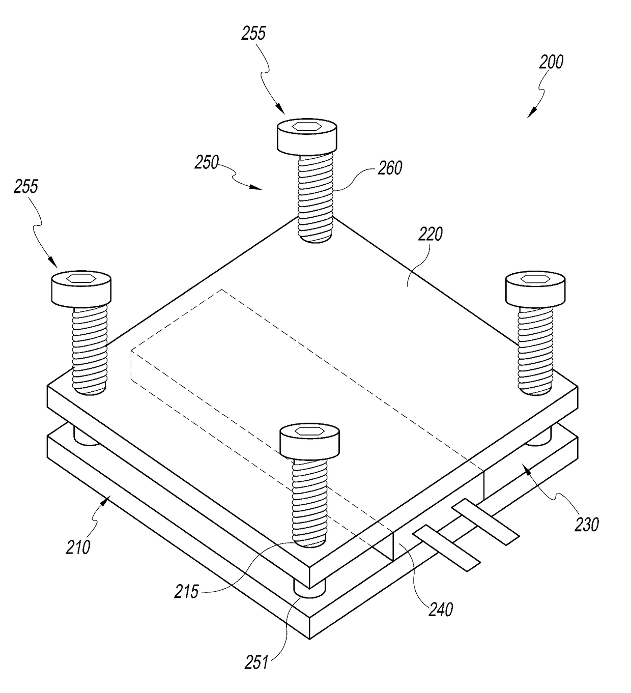
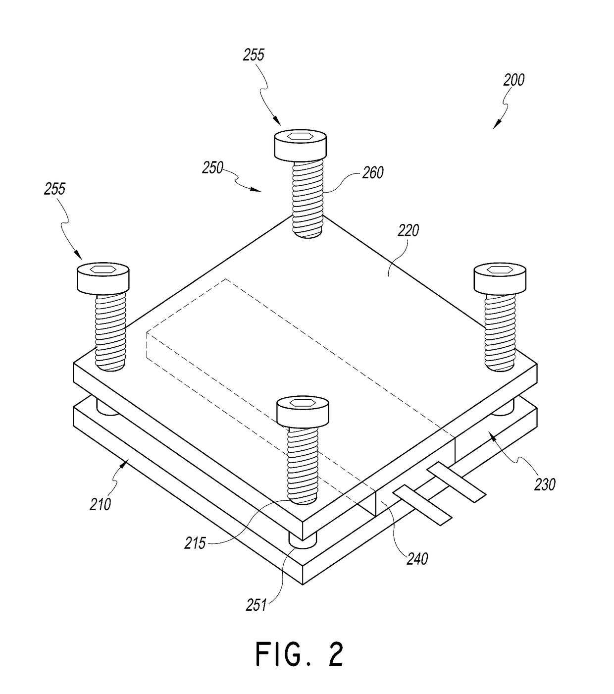
[0020]This disclosure describes certain embodiments of a clamping device for an electrochemical cell stack configured to reduce deformation of an electrode that expands in...


PUM

PropertyMeasurementUnit
thicknessesaaaaaaaaaa
pressureaaaaaaaaaa

Abstract

A clamping device for an electrochemical cell stack is provided. The clamping device can include a first plate and a second plate. The second plate can be positionable relative to the first plate such that a space between the first plate and the second plate can be sized to receive an electrochemical cell stack. The device also can include a coupling member coupling the first plate to the second plate. At least one of the first and second plates can be movable away from the other plate. The coupling member can have a first end portion and a second end portion. The device further can include an elastic member disposed between the first end portion and the second end portion.

Description

CROSS-REFERENCE TO RELATED APPLICATIONS[0001]This application claims the benefit of U.S. Provisional Patent Application No. 61 / 785,728, filed Mar. 14, 2013, which is incorporated in its entirety by reference herein.BACKGROUND[0002]Field[0003]The present disclosure relates generally to clamping devices. In particular, the present disclosure relates to clamping devices for electrochemical cell stacks.[0004]Description of the Related Art[0005]A lithium ion battery typically includes a separator and / or electrolyte between an anode and a cathode. In some of batteries, the separator, cathode and anode materials are individually formed into sheets or films. Sheets of the cathode, separator and anode are subsequently stacked or rolled with the separator separating the cathode and anode (e.g., electrodes) to form the battery. For the cathode, separator and anode to be rolled, each sheet must be sufficiently deformable or flexible to be rolled without failures, such as cracks, brakes, mechani...

Claims


Application Information

Patent Timeline
Patent Type & Authority Patents(United States)
IPC IPC(8): H01M8/02H01M10/0525H01M4/134H01M2/10H01M10/44H01M10/04H01M10/058H01M50/211
CPCH01M10/0468H01M2/1061H01M2/1077H01M4/134H01M10/058H01M10/0525H01M10/441H01M10/446Y02E60/122Y10T29/49108Y02E60/10Y02P70/50H01M50/211H01M50/209H01M50/20H01M10/0481
Inventor TURON TEIXIDOR, GENISSCHANK, STEPHEN W.PARK, BENJAMIN YONGZAOUK, RABIH BACHIR
Owner ENEVATE CORP
Why Eureka
Try Eureka