LED retrofit lamp

a technology for retrofitting lamps and led lamps, which is applied in the direction of lighting safety devices, semiconductor devices for light sources, lighting and heating apparatus, etc., can solve the problems of no hf signal, no regular or sufficient hf signal, and devices that remain non-conducting, and achieve the effect of less cos

Active Publication Date: 2017-04-11
SIGNIFY HLDG BV
View PDF14 Cites 29 Cited by
  • Summary
  • Abstract
  • Description
  • Claims
  • Application Information

AI Technical Summary

Benefits of technology

[0016]The LED unit may certainly comprise further electric or electronic components, such as a driver unit, e.g. to set the brightness and / or color, rectifying circuitry, a smooting stage, a filter capacitor and / or a discharging protection diode. The LED unit may comprise more than one LED, for example in applications where colour-control of the emitted light is desired, e.g. using RGB-LEDs, or to further increase the luminous flux of the LED lamp. Furthermore, the LED lamp may comprise more than one LED unit.
[0020]According to a preferred embodiment, said control unit is further adapted to set said first and second switching devices at least temporarily to a non-conducting state in response to a power reduction on said mains current line. Thus, upon disconnecting one end of the TL tube lamp with the respective fixture, current on the mains current line stops flowing. Such change on the mains current line may be detected, e.g., by the control unit. The control unit then changes the state of the first and second switching devices from conducting to non-conducting. Accordingly, the two ends of the LED retrofit lamp are insulated from each other, because no current may flow along the first and second switching devices along the mains current line. Thus, a user attempting to de-install the lamp according to a preferred embodiment of the invention does not risk receiving an electrical shock by touching the contacts at one end of the lamp if the other end of the lamp is still connected to power.
[0034]According to a further preferred embodiment, during said startup mode of operation, said control unit is further adapted to convert said ignition voltage to an initial supply voltage and to provide said initial supply voltage to the first and second switching devices. The first and second switching devices are adapted to change to a conducting state upon receipt of said ignition voltage. The ignition voltage may be provided directly to the first and second switching devices in order to change their respective states from non-conducting to conducting. Accordingly, the circuitry can be kept simple because no additional startup circuit is required to set the first and second switching devices conducting.
[0037]According to a further preferred embodiment, the control unit comprises a voltage supply unit, said voltage supply unit being adapted to provide a supply voltage to the first and second switching devices; said voltage supply unit comprising a shunt supply circuit adapted to tap energy from said mains current line during a steady-state mode of operation. The shunt supply circuit comprises a full diode bridge and a shunt switch; and / or an active full bridge comprising at least two diodes and at least two MOSFETs; and / or an asymmetrical half-bridge. When the switch (or the MOSFET) is in a conducting state, the mains current path is bypassed. When the switch (or the MOSFET) is n a non-conducting state (i.e., turned off), the main current may be used, e.g., to charge a filter capacitor. Accordingly, it is possible to regulate the low supply voltage by controlling the state of the switch (or of the MOSFET). The accordingly regulated supply voltage may then be used to provide energy to the switching devices. In particular, if the switching devices comprise first and second relays, the regulated supply voltage may provide energy to the respective relay coils. Preferably, the shunt supply circuit comprises an asymmetrical half-bridge, because such circuitry comprises fewer components and incurs less costs.

Problems solved by technology

If on the other hand, only one end of the tube lamp is inserted into the fixture, in most cases no HF signal is generated by the ballast and in some cases no regular or sufficient HF signal is provided on the mains current line and the first and second switching devices remain non-conducting.
That is to say, some ballast generates some ignition voltage in the situation when the lamp is connected to the “hot” side of the ballast output, but such ignition voltage will only last for a short time.

Method used


Image

  • LED retrofit lamp
  • LED retrofit lamp
  • LED retrofit lamp

Examples


Embodiment Construction

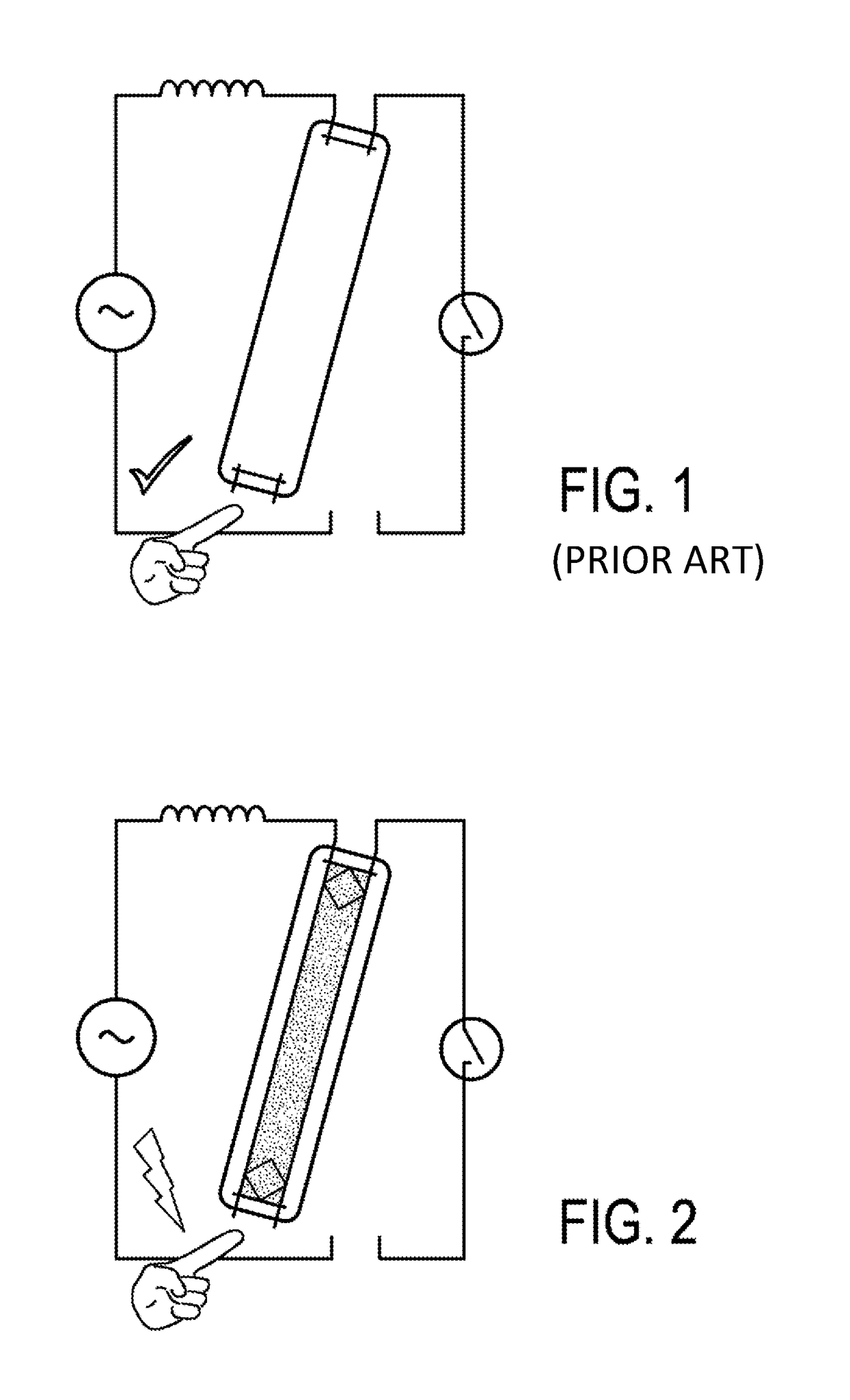
[0060]FIG. 1 shows schematically and exemplarily an example of a conventional TL-tube. Conventional TL tube lamps are safe due to the fact that the gas inside the tube first has to be ignited before there is a conducting path between the two connections on the end of the tube. Ignition is carried out via a combination of starter and ballast or a HF generated high voltage. This safety is necessary when the tube is being installed into a fixture while the voltage is not disconnected from the mains. In the situation when the lamp is not inserted correctly (e.g., one side inserted and the other not yet), the one side of the lamp is connected to live mains and the electrical contacts of the other side are insulated from the live mains As illustrated by FIG. 1, the pins of a conventional TL-Tube are safe to touch.

[0061]However, upon using LED-based lamps, such as LED-based retrofit lamps, there is a conducting path between the electronics in the two ends of the tube. Thus, safety is not g...


PUM


Abstract

The present invention relates to an LED retrofit lamp (700) adapted for operation with an alternating current. The LED lamp comprises an LED unit (740), a mains current line, first and second switching devices (710, 720) (e.g., first and second relays), and a control unit (730). The control unit (730) detects an ignition voltage on the mains current line. In response to detecting the ignition voltage on the mains current line, the control unit (730) sets the first and second switching devices (710, 720) to a conducting state such that the LED unit (740) is connected to power. By using the first and second switching devices (710, 720), safety of the LED lamp (700) is improved, in particular when installing the lamp (700) into a fixture designed for fluorescent lamps.

Description

CROSS-REFERENCE TO PRIOR APPLICATIONS[0001]This application is the U.S. National Phase application under 35 U.S.C. §371 of International Application No. PCT / EP2014 / 068434, filed on Aug. 29, 2014, which claims the benefit of European Patent Application No. EP13182262.9 filed on Aug. 29, 2013. These applications are hereby incorporated by reference herein.FIELD OF THE INVENTION[0002]The invention relates to an LED retrofit lamp and to a method of operating an LED retrofit lamp with an alternating current.BACKGROUND OF THE INVENTION[0003]WO2012127371A1 discloses an electric lamp having two pairs of external connection pins adapted for connecting the lamp to a voltage source for powering an internal lighting module. Each pair of pins is disconnected from the lighting module by an open switch unless a non-zero electric voltage is applied to the pair and causes the switch to close. The lamp may be fitted in a switch-start fixture, providing an ohmic connection between two pins in differen...

Claims


Application Information

Patent Timeline
Patent Type & Authority Patents(United States)
IPC IPC(8): H05B33/08F21V23/06F21V25/04F21K9/27H05B44/00
CPCH05B33/0884F21K9/27F21V23/06F21V25/04H05B33/0803H05B33/0809H05B33/0842Y02B20/383Y02B20/386F21K9/278Y02B20/30H05B45/3578H05B47/26H05B45/00
Inventor ACKERMANN, BERNDTAO, HAIMINSAUERLAENDER, GEORGVAN DIJK, BERNHARD CHRISTIAANSU, BORONG
Owner SIGNIFY HLDG BV
Why Eureka
Try Eureka