Cell partitioning for high-speed users

a high-speed user and cell technology, applied in power management, electrical equipment, transmission, etc., can solve the problems of high-speed user mobility management, inefficiency at high speeds, and inability to arbitrarily reduce, so as to achieve the effect of reducing the complexity of implementation

Inactive Publication Date: 2017-04-18
ALCATEL LUCENT SAS
View PDF15 Cites 1 Cited by
  • Summary
  • Abstract
  • Description
  • Claims
  • Application Information

AI Technical Summary

Benefits of technology

[0015]It is an object of the present invention to provide a solution that is efficient whatever the user speed, that requires minimum implementation complexity, and that is not restricted to specific wireless network architectures.
[0020]Transmit power is adapted to the user speed class, with notably high transmit power for high-speed users. Large-radius radio coverage areas with boosted transmit power handle fast-moving users, such as motorists, while small-radius radio coverage areas with nominal transmit power keep on handling slow-moving users, such as pedestrians. In this way, high-speed users remain attached to the same cell for a longer duration, which prevents intractable frequent handovers.

Problems solved by technology

However, operating high density of picocells raises major issues not only in terms of radio interference but also in terms of mobility management.
In this context, guaranteeing a steady QoE to high speed users moving through picocells becomes challenging: cell reselection, Radio Resource Control (RRC) reconfiguration, attachment to the new cell have to be performed in a very short time to maintain call connection and to avoid Radio Link Failures (RLF).
However, it proves inefficient at high speeds.
So, handover measurements and Time-To-Trigger (TTT) handover have to account for these radio fluctuations and cannot be arbitrarily reduced.
Added to this, implementation complexity arises from the construction and selection of the VC.

Method used


Image

  • Cell partitioning for high-speed users
  • Cell partitioning for high-speed users
  • Cell partitioning for high-speed users

Examples


Embodiment Construction

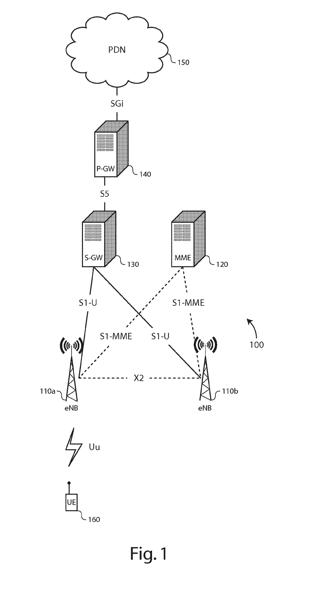
[0044]There is seen in FIG. 1 a part 100 of LTE Radio Access Network (E-RAN) and an Evolved Packet Core (EPC) comprising the following network elements:[0045]Evolved NodeB (eNB) 110,[0046]a Mobility Management Entity (MME) 120,[0047]a Serving Gateway (S-GW) 130,[0048]a Packet Data Network (PDN) Gateway (P-GW) 140,[0049]a PDN 150, and[0050]a UE 160.

[0051]The eNBs 110 are coupled to the MME 120 through an S1-MME interface, and to the S-GW 130 through an S1-U interface. The S-GW 130 is further coupled to the P-GW 140 through an S5 interface. The P-GW 140 is further coupled to a PDN 150 through an SGi interface. The eNBs 120 establish neighbor relationships with neighboring eNBs through an X2 interface.

[0052]The eNBs 110 operate micro or pico cells with a small and confined coverage area, typically from a few tens meters up to a few hundreds meters. The eNBs 110 are configured to set up and operate a radio communication channel (i.e., a set of downlink and uplink traffic radio resources...


PUM


Abstract

The present invention relates to a radio access arrangement for operating a radio cell (C), and comprising at least one wireless transceiver (210) configured to set up and operate radio communication channels with mobile devices. In accordance with an embodiment of the invention, the radio access arrangement further comprises speed determination logic (240) configured to characterize a particular mobile device (320) as belonging to a high-speed or lower-speed category (HS; LS) according to speed information of the particular mobile device, and a radio resource controller (250) configured to assign a particular radio communication channel, for communication with the particular mobile device, within a first or second disjoint radio resource partition of the radio cell (B_DL1; B_UL1; B_DL2; B_UL2) if the particular mobile device is characterized as belonging to the lower-speed or high-speed category. The radio access arrangement further comprises a transmit power controller (213) configured to control a transmit power used for communication over the particular radio communication channel as being lower than a first or second substantially higher maximum transmit power level (PTXMAX_DL1; PTXMAX_UL1; PTAX_MAX_DL2; PTXMAX_UL2) if the particular radio communication channel is assigned within the first or second radio resource partition respectively, thereby yielding a long-reach radio coverage area (340) for high-speed mobile devices and a shorter-reach radio coverage area (330) for lower-speed mobile devices. The present invention also relates to a method for operating a radio cell, and to a method for configuring radio resources of radio cells.

Description

TECHNICAL FIELD OF THE INVENTION[0001]The present invention relates to mobile communications, and more specifically to handover of high-speed users moving across short-radius cells.TECHNICAL BACKGROUND OF THE INVENTION[0002]Thanks to higher spatial reuse of spectrum, short-radius cells (further shortened as picocells) appear as a promising 4th Generation (4G) solution to satisfy bandwidth extensive traffic demands and to enhance the Quality of Experience (QoE) of mobile users.[0003]However, operating high density of picocells raises major issues not only in terms of radio interference but also in terms of mobility management. Given the short distance separating neighbouring picocells, high speed users are expected to cross a large number of picocells in a short time frame. Indeed, the handover rate increases with the user speed and with the inverse of the inter-cell distance.[0004]In this context, guaranteeing a steady QoE to high speed users moving through picocells becomes challen...

Claims


Application Information

Patent Timeline
Patent Type & Authority Patents(United States)
IPC IPC(8): H04B13/02H04W16/32H04W36/00H04W52/38H04W64/00H04W52/14H04W52/36H04W36/32
CPCH04W36/0066H04W16/32H04W52/146H04W52/367H04W52/38H04W64/006H04W36/32H04W52/04H04W72/04H04W88/08
Inventor CAPDEVIELLE, VERONIQUEALTMAN, EITANRAMANATH, SREENATHROULLET, LAURENT
Owner ALCATEL LUCENT SAS
Why Eureka
Try Eureka