
Projector with series positioned pixel matrices

a projector and pixel matrice technology, applied in the field of projectors, can solve the problem that it is not always easy to maintain the image formation state in a small size, and achieve the effects of good telecentricity, high performance and small siz

Inactive Publication Date: 2017-04-25
SEIKO EPSON CORP
View PDF13 Cites 0 Cited by
  • Summary
  • Abstract
  • Description
  • Claims
  • Application Information

AI Technical Summary

Benefits of technology

[0006]An advantage of some aspects of the invention is to provide a projector which includes a first pixel matrix and a second pixel matrix which are two spatial modulation elements arranged in series on an optical path, and can maintain an image formation state in a small size, with good telecentricity, and with high performance.
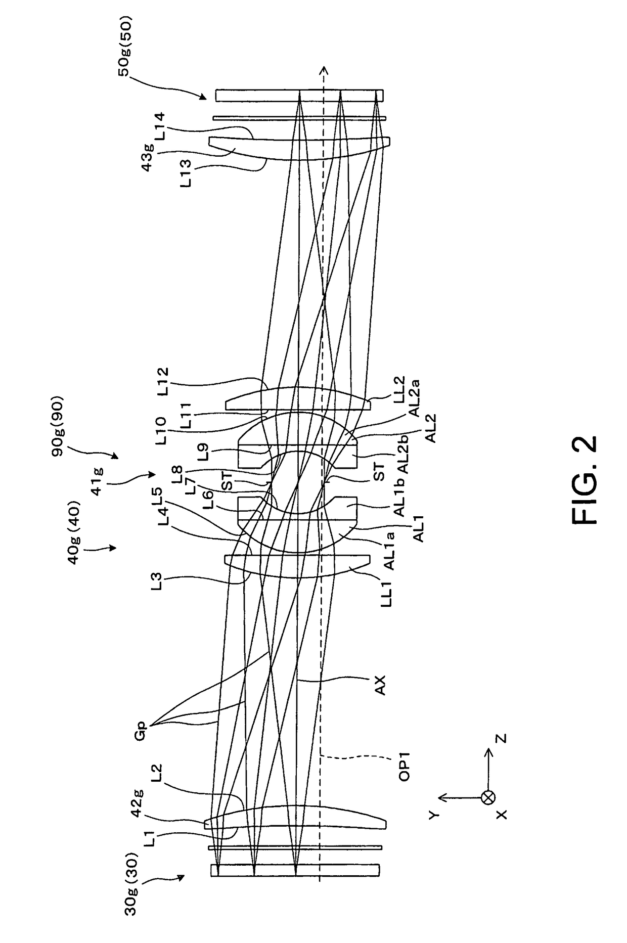
[0008]According to the projector, the relay optical system which relays image formation between the first pixel matrix and the second pixel matrix includes the pair of meniscus lenses having a positive power as well as the double gauss lens. In addition, the meniscus lenses are disposed with the double gauss lens interposed therebetween along the optical path, and are disposed so as to be convex toward the double gauss lens side. Thus, it is possible to prevent a size of a device from being increased, to make telecentricity favorable, and to improve image formation performance of the optical system in which two pixel matrices are disposed at conjugate positions.
[0009]In a specific aspect of the invention, the relay optical system includes a diaphragm at the double gauss lens, and is an optical system of equal magnification which is symmetric with respect to a position of the diaphragm along an optical axis. In this case, since the relay optical system is symmetric with respect to a position of the diaphragm, for example, pixel matrices having the same standards are used as both the two pixel matrices, and are equivalently disposed, so as to minimize coma aberration and distortion aberration. In addition, field curvature aberration and astigmatism are minimized by using the meniscus lenses, and thus it is possible to implement a high performance relay optical system.
[0010]In another aspect of the invention, the first and second pixel matrices are transmissive liquid crystal pixel matrices. In this case, it is possible to form a bright image with a simple structure. In addition, the pair of meniscus lenses can be disposed so as to be close to the first and second pixel matrices, and thus it is possible to improve an aberration correction function using the meniscus lenses.
[0013]In this case, both-side telecentricity can be achieved in the relay optical system, and it is possible to achieve a sufficient aberration correction effect using the meniscus lenses.
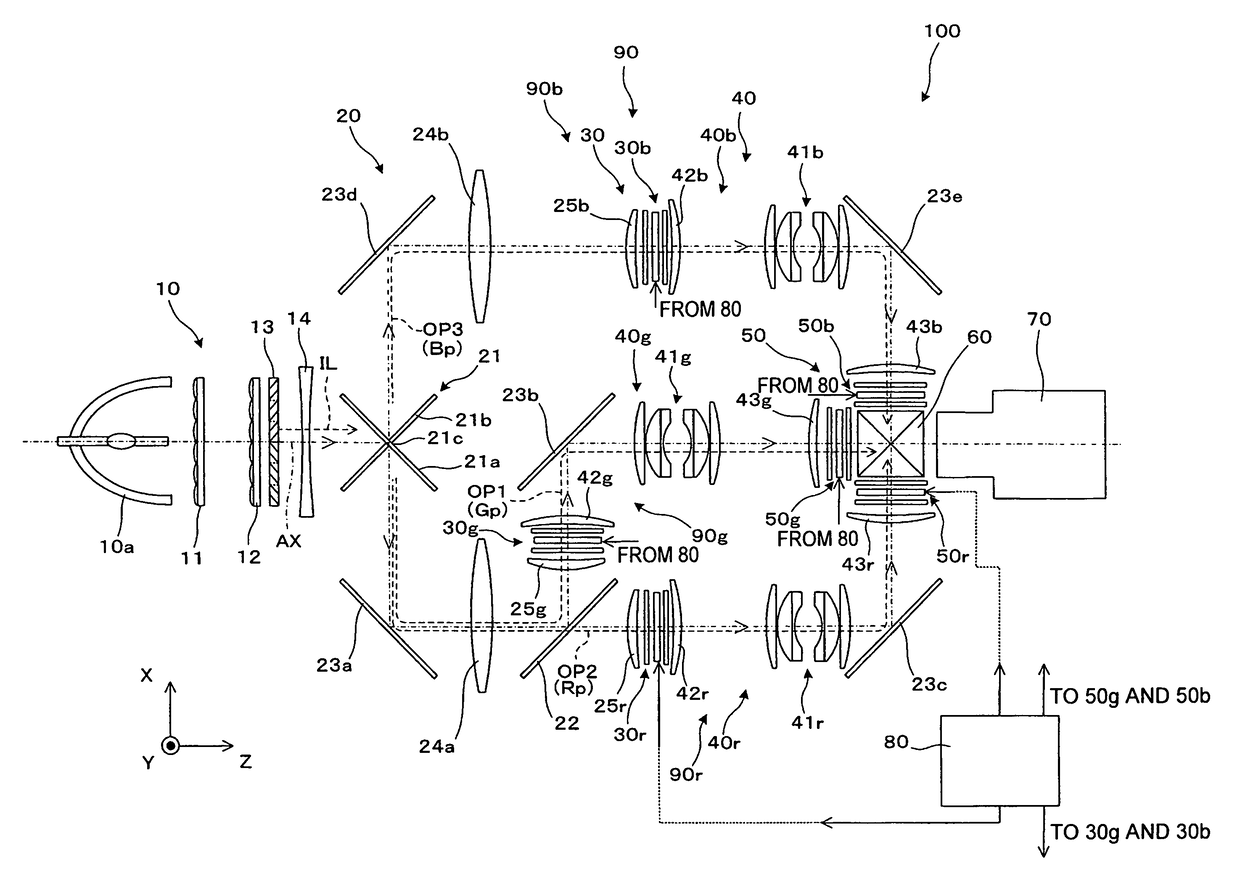
[0015]In still yet another aspect, the color splitting / light guide optical system and the modulation optical system are disposed so that optical paths of the plurality of color light beams from splitting of the light in the color splitting / light guide optical system to combination of the light beams in the composition optical system are in an equal optical path length. In this case, it is possible to prevent the occurrence of color unevenness caused by the number of inversions of color light. In addition, in the configuration in which the first pixel matrix and the second pixel matrix are provided, an entire device can be made relatively compact.

Problems solved by technology

However, even if aberration is minimized to an extent by using the double gauss lens as the relay lens between the two spatial modulation elements as described above, a variety of aberrations (for example, a field curvature or astigmatism) cannot be sufficiently minimized, and it is not necessarily easy to maintain an image formation state in a small size, with good telecentricity, and with high performance.

Method used


Image

  • Projector with series positioned pixel matrices
  • Projector with series positioned pixel matrices
  • Projector with series positioned pixel matrices

Examples


first embodiment

[0026]Hereinafter, with reference to the drawings, a projector related to each embodiment of the invention will be described in detail.

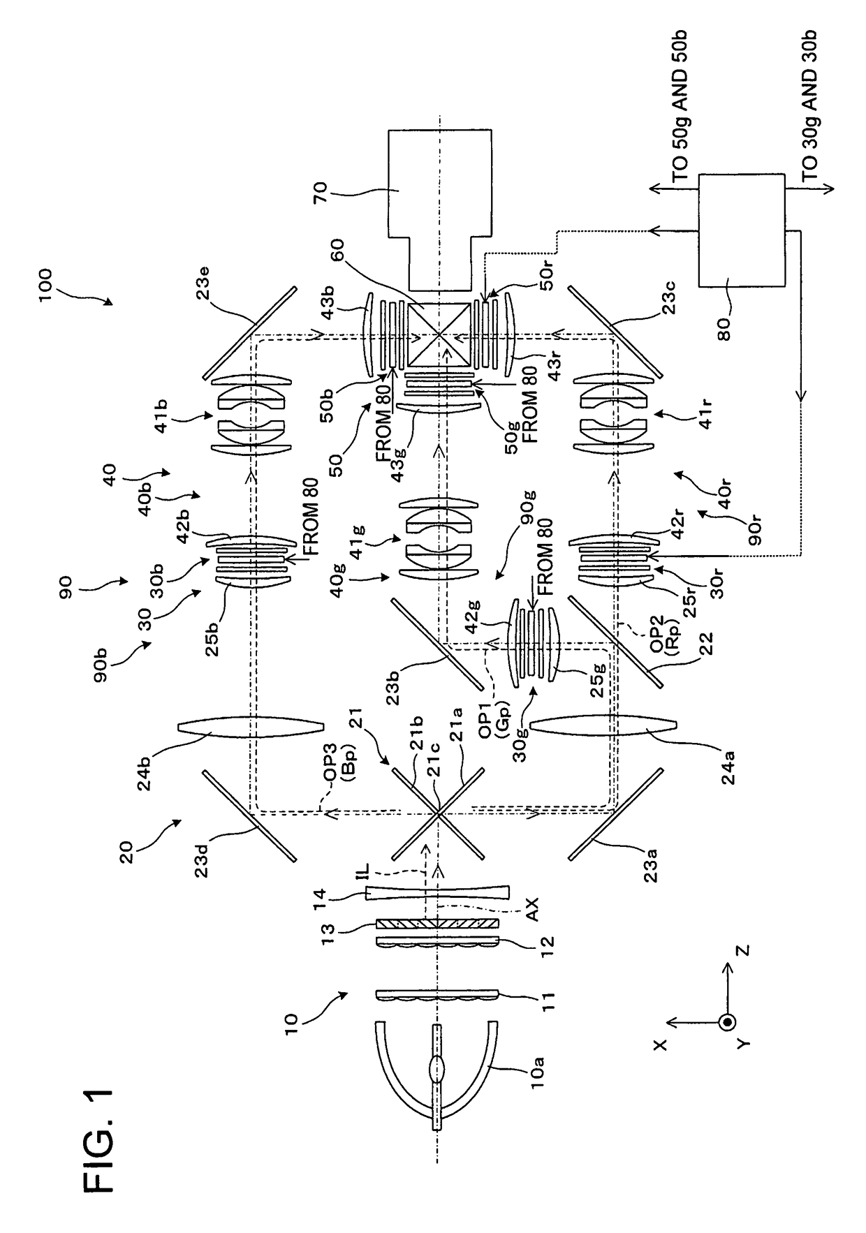
[0027]As illustrated in FIG. 1, a projector 100 according to a first embodiment of the invention includes an illumination optical system 10 which emits illumination light; a color splitting / light guide optical system 20 which separates the illumination light into a color light beam of each color and guides the color light beams; a modulation optical system 90 which spatially modulates each color light beam which is emitted from the illumination optical system 10 and is separated by the color splitting / light guide optical system 20; a composition optical system 60 which combines the separated and modulated color light beams (modulated light beams) with each other; a projection optical system 70 which projects the combined light; and a projector controller 80. Among the above-described optical systems, particularly, the modulation optical system 90 inc...

example 1

[0057]Data of optical surfaces constituting a relay optical system of Example 1 is shown in the following Table 1. In addition, Table 1 and 2 also illustrate lenses of Example 1. Further, in FIG. 1, a “surface number” is a number which is given to each lens surface in order from a field side. Furthermore, “LP” added after the surface number indicates a position of a liquid crystal panel, “PP” indicates a position of a polarization plate, and “ST” indicates a position of a diaphragm. Moreover, a numerical value subsequent to E indicates an exponent part of base 10, and, for example, “1.00E+18” indicates 1.00×10¹⁸.

[0058]

TABLE 1SurfaceNumberRDNdνd 1(LP)1.00E+182.31.5168064.17 21.00E+183 3(PP)1.00E+180.71.5168064.17 41.00E+184 5−2.20E+0241.8466623.8 6−52.924545 735.383694.51.8044039.6 81.00E+180.5 914.668846.51.7995242.2101.00E+181.21.7618226.5119.3897416.1612(ST)1.00E+186.1613−9.389741.21.7618226.5141.00E+186.51.7995242.215−14.66880.5161.00E+184.51.8044039.617−35.383745185.29E+0141.846...

second embodiment

[0062]Hereinafter, a projector according to a second embodiment will be described. In addition, the present embodiment is a modification example of the projector of the first embodiment, and parts or matters which are not particularly described are the same as those in the first embodiment.

[0063]FIG. 6 is a diagram illustrating a projector according to the second embodiment, and FIG. 7 is a diagram illustrating an example of an optical path which is developed from a first liquid crystal pixel matrix to a second liquid crystal pixel matrix and corresponds to FIG. 2 of the first embodiment. In addition, in a case of a configuration of FIG. 6, optical paths of respective color light beams are in an equal optical path length.

[0064]As illustrated in FIGS. 6 and 7, a relay optical system 240 of a projector 200 of the present embodiment has a structure different from that of the relay optical system 40 of the projector 100 of the first embodiment in the same manner as in FIG. 1. Specifical...


PUM

PropertyMeasurementUnit
wavelength bandsaaaaaaaaaa
focal lengthaaaaaaaaaa

Abstract

Since a relay optical system includes double gauss lenses and pairs of meniscus lenses disposed so as to be convex toward the double gauss lenses, it is possible to sufficiently minimize the occurrence of aberration from dimming light valves to color modulation light valves, to maintain an image formation state with high performance, and further to form a favorable image.

Description

BACKGROUND[0001]1. Technical Field[0002]The present invention relates to a projector including a first spatial modulation element and a second spatial modulation element which are disposed in series on a light path.[0003]2. Related Art[0004]A projector is known in which two spatial modulation elements are arranged in series in order to increase image contrast (refer to JP-T-2006-509244, JP-A-2005-189282, and JP-A-2005-208573). In this case, a relay lens is disposed between the two spatial modulation elements, and one image of the two spatial modulation elements is superimposed on the other image so as to form an image. Particularly, in JP-T-2006-509244, when an image is formed between two spatial modulation elements, a double gauss lens is used as a relay lens.[0005]However, even if aberration is minimized to an extent by using the double gauss lens as the relay lens between the two spatial modulation elements as described above, a variety of aberrations (for example, a field curvat...

Claims


Application Information

Patent Timeline
Patent Type & Authority Patents(United States)
IPC IPC(8): G03B21/00G02F1/13H04N9/31G02B27/14G02B27/10G02B9/62
CPCG03B21/00G02B27/141G02F1/1313G03B21/006H04N9/3152G02B9/62G02B27/1046G03B21/005G03B21/26H04N9/3105H04N9/3126
Inventor OTANI, MAKOTO
Owner SEIKO EPSON CORP
Learn More